When using the viewers several television antennas, receiving signals from different directions on different bands and channels you receive their loss-free transmission to the TV with the best quality. How to solve it, and says the author of a published article.
The problem of high-quality reception of TV programs always concerned viewers, and at the present time it has not lost its relevance, and acquired new dimensions. Thus, in most of cities television broadcasting't already limited to one or two channels. In connection with such rapid growth in their number arise and some new features in the application of antennas.
Since each television channel is running in your lane, MIDs which can vary considerably, it is necessary to use several antennas on different bands. Often the TV signals come from different directions, and not only in rural but also in urban areas. First, for the reason that that transmitters are sometimes located in different parts of the city or in different cities for rural areas. Secondly, sometimes the reflected signal is stronger direct (for example, if in the path of the direct signal is the biggest obstacle). Observed and multiple reflections of the signal. Therefore, the antenna requires spatial orienting in different directions.
In addition, television signals of television stations may have different polarization. Therefore, the antenna must be placed in the respective planes (horizontal or vertical). Besides transmitters are often used vary considerably in power (ten times) or are located on significantly different distances.
These reasons necessitate the use of multiple antennas, each of which, ideally, is configured only on your channel. In such conditions indoor antenna often do not provide acceptable reception quality of all channels, especially the residents of the lower floors of multi-storey buildings in dense of urban development.
In turn, there arises the problem of delivery of received antenna signals TV that can be solved in several ways.
First of all, navigate from each antenna, your cable and manually commute plugs in jacks on the TV. This option is economically significantly not favorable (requires a lot of cable) and uncomfortable (frequent switching plugs leads, eventually, to failure of nests).
Secondly, use of the separation filters or adders operating on one cable reduction. However, with increasing number of antennas of these devices significantly become more complicated. In addition, significantly increasing the loss of useful signal.
Third, switch the antenna cables, remote-controlled devices, located in near (on the roof), and a signal for a single cable reducing. This method can be implemented in several ways. One of them is the use of Electromechanical relays. However, with the increasing number of antennas grows and the influence of the capacity of the switching contacts. In addition, relay consume quite a lot of current. Another way is the use of electronic devices switching, which is devoid of these shortcomings.
Option is a relatively simple eight switch signals television antennas, powered and remotely controlled via a single cable drop, was assembled according to the schematic diagram depicted in Fig. 1.
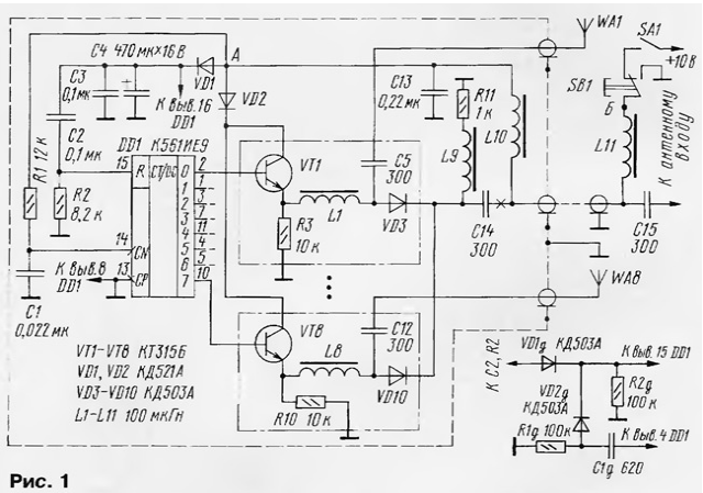
The basis of the device - chip CIE (DD1), which is a counter with the eight decoder outputs. When the power toggle switch SA1 through it the button SB1, the inductor L11, located near the TV, cable, the inductor L10 and the diode VD1 is charging the capacitor C4, and the voltage is supplied to the chip. At first the supply voltage passes through the capacitor C2 to the reset input R of the chip DD1 and sets a counter to initial (zero) state. Thus at its output 0 (pin 2) appears level 1, and outputs 1 - 7 - level 0. Transistor VT1 emitter follower the first of the eight transistor-diode cells will be opened and transistors VT2-VT8 other cells are closed. The diode VD3 is applied opening the voltage through the inductor L9 and resistor R11 the current flows. On diodes VD4 - VD10 enters the closing voltage.
When open, the diodes have a low resistance is equal to the units of ohms, and in the closed state is a high resistance and small capacity not exceeding one picofarad. As a result, through the capacitor C5, open diode VD3, capacitors C14, C15 and cable reduce the high-frequency signal from the antenna WA1 comes to the input of the TV. Capacitors C5, C14, C15 are used for decoupling DC and inductors L1 - L11 - decoupling at high frequency signal.
When you press the SB1 supply voltage at the switch and, consequently, the collectors of transistors VT1 - VT8 is not received. In this case, the diode VD1 does not allow to discharge the capacitor C4 via the button connecting the power circuit switch common wire. In this state, the discharge current of the capacitor C4 is determined the current consumption of the circuit and the current through the emitter junction of one of transistors (in our case, VT1). Input CN of the counter DD1 front is formed a negative pulse.
When you release the button SB1, the voltage will again arrive at the switch and on input CN of the counter there is a decline of negative pulse which triggers the change in his condition. Now output 1 (output 1) will be level 1, and the outputs 0, 2 - 7 - level 0. To the input of the TV is connected the WA2 antenna and the other antenna is disabled. Capacitors C1, C13 eliminate the impact of the bounce of the contacts button SB1.
Therefore, short-term pressing the button, you can remotely control connection of the antennas on the ring.
If you want to switch 8, and 10 of the antennas used in the chip CIE, increasing accordingly the number of transistor-diode cells. If antennas less than eight, for example, five, the output circuits whose number corresponds to the number of antennas (in our example the fifth), is connected through a node diagram is presented on Fig. 1 the bottom right, and unnecessary transistor-diode cell removed (from outputs 5 - 7). Then when you are level 1 at the output 5 it is ensured that the counter to the initial (zero) state and will connected antenna WA1.
The device is fitted in a metal casing (I used a metal jar diameter 70 and a height of 23 mm). Details C5-C14, L1 - L10, VD3-VD10 mount hinged manner, and the rest on a small printed circuit Board, which because of the simplicity not represented. It is desirable that the conclusions of the elements on which passes high-frequency signals were of minimum length.
The device incorporates resistors MLT-0,125, capacitors CD-1 or CT-1 (C5 - C12, C14, C15), K50-16 or imported (C4) and K10-17 (C1 - C3, C13). Chokes L1 - L11 - DM-0,1.
Diodes VD1, VD2 - KD521 with any letter index or similar, VD3 - VD10 - diodes with the lowest junction capacitance in the closed state, for example, in addition to specified in the scheme, CDA, KDA, KDA, KDA, KDA or CAA (with open resistance 1...2 Ohms and having a closed state capacity in a fraction of a picofarad). Transistors VT1 - VT8 - KT315 with any letter index. These chips can be substituted with other series, for example, 564.
If the cable is long and the signal is strongly attenuated in the device add common to all antennas wideband RF amplifier industrial manufacture or amplifier assembled in one of the schemes described in the journal. You should choose an amplifier with a supply voltage close to nominal for switch (10 ±10%), although for chip series C allowed voltage the power within 3...15 V. where to connect the amp to the switch marked cross. The amplifier include the scheme in Fig. 2 in the open circuit.
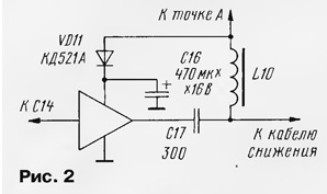
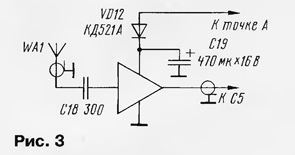
Diode VD11 and the capacitor C16 is optional and is used for a more gentle mode amplifier when the manipulation button SB1. In addition, the amplifier can be used as for any one antenna, and each antenna. The connection shown in Fig. 3.
You can commute and a larger number of antennas, increasing accordingly the number of counters, but the device will be more complex. It should also be borne in mind that with increasing their number increases the influence of the total capacity of the closed diodes.
Increasing the number of switchable antennas is also possible through the use of the separation filters and adders included at the inputs of the switch. For example, you can connect the antenna bands MB (WA1a) and DM In (WA1b) the scheme in Fig. 4.
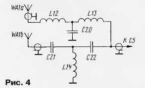
In addition, instead of the signals of television antennas on the switch can be fed and cable television signals or the signals from the antennas broadcasting УSW ranges.
Such a switching system can be supplemented and led indicator numbers or the titles included antenna. It is installed in the vicinity of the button management. It works on the same principle as the switch antennas. Schematic diagram of the indicator depicted in Fig. 5. He switched synchronously with the switch.
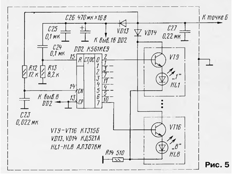
With a smaller number of antennas (less than eight) indicator change so the same as the switch.
Author: O. Bobrov, Voronezh


