


")

The use of UHF waves for the reception of television provides the hams wide possibilities of designing antennas of various types. However, due to the propagation of waves of this range, should focus on the manufacture of high-performance antennas with a narrow beam. Described in this paper antenna belongs to this class. She has a Directive gain (KND) around 50 and comparatively easy to manufacture. At its base is a lozenge fabric, which is well known for use in high frequency range.
The main disadvantages of rhombic antenna of usual type are low efficiency due to the inclusion of the active load resistance and the presence of the directional diagram of the significant side lobes. To increase the antenna gain by excluding active load and expanding the transverse dimensions of the wires of a rhombus since it leads to additional growth of the side lobes. Almost completely get rid of the first fault (i.e., to increase efficiency of approximately 100%) and significantly weaken the second (lower the sidelobe level), load rhombic canvas is active, the variable reactive load, and supplying the antenna with reflector (Fig. 1).
Fig. 1
The operation of the antenna can be represented as follows: under the action of excitatory E. D. S. on the wires of the diamond occurs incident wave propagating in the direction of the reactive load and creates the field Epad (Fig. 1). Part of the energy of this wave goes to radiation, and the remaining part is totally reflected a reactive load on the wires and creates a diamond pattern reflected wave propagating in the side of the screen - reflector. This wave creates a field Eotr. In turn some of the energy of the reflected wave is radiation, and the remainder is absorbed by the generator, and greatly EMF Field of the reflected wave incident on the reflector that changes the propagation direction and is superimposed on the incident wave field. When changing reactive load conditions change in the overlay and in the end the resulting field Via can
to be the optimal conditions. Obviously, they depend on the phase of the field Eotr and its amplitude. Phase field Eotr selected a reactive load, and the amplitude is set by the diameter of the wires of a rhombus. Note: a portion of the energy wave reflected from the reactive load that enters the feeder, can be used to compensate for the reflections at the input, arising due to the difference between the characteristic impedance of the feeder and input impedance of the antenna that can improve the coordination between the antenna feeder.
Conditions for optimal resulting field Erez and mode of operation of the feeder close to each other, so at the same time more necessary directional pattern ensures consistency between the antenna feeder.
The directional rhombic antenna with reflector and variable reactive load for l=3L and angle f=113° shown in Fig. 2. As can be seen from this figure, for E-plane (horizontal) angle of aperture of the beam is small (15°). It requires more attention when adjusting the antenna.
Fig. 2
Structurally, the antenna can be made as shown in Fig.3. It consists of a flat lattice reflector, rhombic leaf, node power and retainers (cages and braces). All the details of the reflector, including the mast can be made of metal. If this is not possible, then cross rail 1 reflector and barrel 2 masts can be made of wood, and other parts - of the wire. It is advisable to delay the mast trunk stretch marks 3 the ends of the upper and lower transverse rails of the reflector to prevent sagging of the wires.
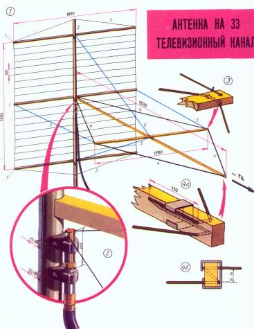
Fig.3
Rhombic canvas 4 antennas are made of bare copper wires with a diameter of about 1 mm. It is attached to the ends of the dielectric (wooden) frame. The plane of the frame should be parallel to the plane of the earth and perpendicular to the plane of the reflector. To fix the frame using four brace 5. And the frame, and braces must be made of dielectric. For the frame it is convenient to use ski poles out of bamboo, cane or fiberglass. Braces can be made of several lived nylon fishing lines. If you will apply a wooden frame, it is necessary at the point of immediate contact with the wires rhombic leaf to provide for the insertion of organic glass. All hardware except for the nodes, described below, can be made arbitrarily from the materials available to the radio Amateur.
In Fig. 3.2 shows a diagram of the power antenna. It provides the transition from coaxial cable RK-75-7-15 (RC-3) to the wires of a rhombus. This transition (balun device) is a tube with two slots. The width of the grooves is 0.4 inner diameter of the tube, the length is about 250 mm end of the cable is inserted into the tube on the side opposite the grooves so that its outer braid was stretched on the tube. On top of the braid impose a tie and probailout tube, braid and bandage. Then the exposed portion of the braid and the bandage is wrapped with insulation tape. Extended from the second end of the tube (grooves) of plastic insulation from the center conductor is cut and the last soldered to one half of the tube, formed after slotting. Wire rhombic leaf soldered to both halves of the tube and reinforcing node formed directly on the trunk of the mast, as it accounts for a big load - tension wires of a rhombus. Before you solder the conductors of the diamond to the halves of the tube, tightly wear metal ring (movable shorting), terminating short of the half tube and allowing to change the length of the grooves from the feed points of the diamond to the ring. Attach the tube along the trunk of the mast should be on the dielectric strips (PCB, organic glass), so that between the tube and the barrel was in the lumen of 20-30 mm. Bind the receiver to the mast can only dielectric materials, such as nylon fishing line. The fastening grooves below can be done with wire. In the ends of the transverse frame rails of a rhombus insert plastic, ceramic or glass spigot (Fig. 3.3). They insert a wire rhombus.
In opposite to the feed point to the top of the diamond shall be loaded on a variable reactive load. It is a closed one end with two wire line formed by the continuation of the sides of a rhombus (Fig. 3.4,a). You should avoid the location of this line on a wooden frame. Thus, the end of longitudinal frame rails of the diamond should be made of organic glass or other insulating material. In order to have the ability to change the length of the line, you need to make and to wear her brace-shorting (Fig. 3.4, b).
To begin configuring the antenna should be a gradual change in the length of the two-wire load line by moving the ring-shorting at the feed point of the rhombus so that the length of the grooves was equal to a quarter wavelength (131 mm). To assess the proper configuration of the antenna is better on the radiation patterns, which should be as close as possible to that shown in Fig. 2. If it is not possible to determine the directivity, the antenna operation is determined by the quality of the image on the TV screen.
Because in the beginning settings shorting clip two-wire line is set arbitrarily, in the direction of the main radiation of the antenna can be a failure. It is not difficult to detect, rotate the antenna left or right by ±20° from the direction to the correspondent. In this case, without directing the antenna on one of the available maximums, should continue the setting. You need to Orient the antenna to fail and to seek its elimination by moving the bracket shorting-along a two-wire line. Picking up the desired position of the bracket is shorting, you need to lock it on the line and adjust the antenna by moving the ring-shorting at the feed point of the antenna up and down from the starting position.
The dimensions of the described antenna can be changed, using the graph Fig. 4, which shows the dependence of the angle f of the rhombus (see Fig. 1) from the length of l/L, expressed in wavelengths. This graph allows you to calculate the required dimensions of rhombic frame for paintings. All other components of the antenna are not changed except for the reflector, the transverse slats which should be somewhat longer than the transverse frame rails of a rhombus.
Fig. 4
Author: K. Kharchenko; Publication: N. Bolshakov, rf.atnn.ru