At independent manufacture UHF antenna you can use described here a simple design and use of improvised materials.
Relatively good propagation of decimeter radio waves through concrete the building structure allows you to receive TV programs in this the range on a simple indoor antenna and often with very good quality, even no direct line of sight of the transmitting antenna. The proposed double triangular the design of the antenna can be made quite quickly. The main materials are sheets of corrugated cardboard from packaging boxes, household aluminum foil of suitable size, and also coaxial cable with polyethylene insulation (PTFE) and a characteristic impedance of 75 Ohms.
The manufacturing of the antenna starting from the contour of her paintings on sheets of foil and cardboard in Fig. 1 (sharp corners on the edges of acceptable a little trim, figure this is shown by the dashed lines). Then, carefully cut the leaf antenna from foil sheet, is applied a water-based adhesive (for example, "Bustilat", "PVA", etc.) on canvas and cardboard. Aligning with printed outline, paste them to a friend other. Clear the canvas who got it from the adhesive, particularly at the strip cable and electrical connections.
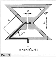
While the glue dries, molded cable in accordance with the routing diagram shown in Fig. 1. To give the cable the necessary forms in bends it carefully heat and subsequent cooling. In this case, try to recast the cable was flat. Further diminish the braid and the center conductor of the cable in places the electrical connections of the canvas of the antenna and making sure that the glue did not get to them, glued the cable to the blade antenna (and if necessary - then to the cardboard) glue "88", "Moment", "Contactor".
After the cable was stuck, tentatively wrapping his braid and the center conductor of aluminium foil strips for reliable contact, connect them with the fabric of the antenna by suturing (three stitches on each connection). When that the thread does not cut the cardboard from the back side glued strip of wood or plastic. The ends of the thread are also fixed with glue. Stand under the antenna can be glued cardboard.
Dimensions double triangular antenna is calculated according to the formulas published in the book by G. I. Boricua and V. I. Bulych "Ham about TV antennas" (M.: DOSAAF, 1977):
L=0,27 λmax (without screen);
L=0,25 λmax (screen);
Δ=0,09 f;
m=0,72 f;
∂=10 mm,
where λmax is the maximum length of a received carrier wave in millimeters.
For example, for the interval of the television channels 21-49 with λmax=to $ 636.6 mm dimensions antenna without the screen turned out to be: L=172 mm, Δ=15.5 mm, m=124 mm, and the antenna with screen - L=159 mm, Δ=14.3 mm, m=115 mm.
The antenna has a coverage ratio specified interval of about 1,45 when IPM>of 0.48 and a gain of about 5 dB. With further increase in frequency the received signal efficiency of the antenna drops.
The screen-reflector - an effective means of strong returns (true, the admission requirements specific need for it is still there). Produce a screen from a continuous sheet of foil, which is glued to a piece of cardboard size 2L(width)x1,75L (height) and are fixed in parallel at a distance of 0.7 L from leaf antenna using U-shaped bent strips of cardboard. For convenience the subsequent Assembly the dimensions of the cardboard sheet with the antenna it is recommended to make such the same as that of the sheet with the screen.
If the signal level at the receive location is small, it can be increased by combining multiple (N) antennas into a simple array. For example, for the four antennas (N=4) is depicted in Fig. 2. Such compounds especially suitable for antennas with internal resistance close to the characteristic impedance of the feeder (in our case - 75 Ohm). Polarity (+ and -) shown conventionally to denote a phase signal. In order to exclude the influence of the antennas of the lattice one distance to another between their webs shall not be less than 90 mm, and to ensure correlation when adding signals the length of the cables from the antennas to the place of their connection should be equal.
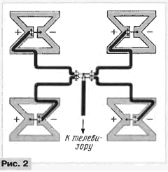
Before deciding on the manufacturing of the antenna complex designs or before acquisition of expensive industrial antenna, it is recommended to prepare the simplest with his own hands, in order to assess in advance the possibility of a satisfactory reception in a specific case.
Should indicate that for an antenna array with N=4 the output voltage will be in two times (+6 dB) compared with single antenna (N=1).
The desirability of using antenna arrays indicates the fact that the use of antenna amplifiers to increase the level of the received signal in combined with modern TVs that have high sensitivity (at enclosed antenna input on the screen is visible noise type falling snow), may not improve the signal-to-noise ratio, since the antenna amplifiers use low noise transistors similar to those used in the channel selectors TV. In such cases, the noise would only be more contrast - and here all.
Of course, arrays are more suitable for open spaces. Besides for specific conditions the relatively high probability of coming-of-phase signal with in-phase and she grows proportionally to the square lattice. Effect is quite the opposite to addition.
To determine the presence of anti-phase signal is pretty easy: just close short conductor braid and the center conductor of the cable to check the the antenna. If the signal has increased (control image on the TV screen), the signal in antiphase, if decreased - in phase. So simply increasing the number of antennas improve reception and can not be achieved.
For N=2 for the purpose of impedance matching of the antenna (150 Ohms) and the input of the TV (75 Ohm) can be used commonly used method in practice broadband inclusion through a variety of LC filters. In Fig. 3 shows the scheme of such approval by the high pass filter. Stripe approvals - 410...914 MHz, uneven AFC - 0,044 dB. Apart from coordination, the filter reduces the signal MB.
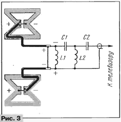
The estimated values of parameters of elements of the filter are as follows: C1=2,32 pF, C2=4,33 pF, L1=48,7 NH, L2=26,1 NH. They are given to three significant figures only for reference - sufficient accuracy ±5...10% of these.
Coils L1 and L2 are frameless. Their design is shown in Fig. 4. They have 4 and 2 turns, respectively, the inner diameters of 4.8 and 3 mm. Step of winding - 2,4 mm, wire petv-2 or similar diameter copper 0.8 mm.
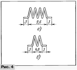
The tubular capacitors - CT-2. If there are no capacitors of suitable capacity and you can easily make yourself. Taking the capacitor with more than need, capacity, her razor reduce to desired uniform removal layer outer metallization (diameter of the capacitor in this place a little more) then grind a piece of emery stone. Measure the capacitance of the capacitor in already molded form, remembering to offset the additional supply capacity conductors.
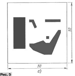
Coated fibreglass is definitely one-sided! Braid cables obluzhivayut and soldered along the entire length of the printed conductor. Should be closer to observe the sizes of printed conductors, as their self-inductance taken into account when calculating the size of the coils.
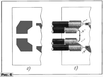
If you need to increase N to 4 (agree 300/75 Ohm), the left part of the print Board change to connect the four cables as shown in Fig. 6. Such inclusion (using the filter) it is sometimes necessary for preventing action too MB powerful transmitters in the UHF selector. To have matching filter directly at the TV and at the point of connection cables the lattice in Fig. 2. In both cases, it is necessary to connect the filter to the antenna cables in accordance with pasirenkami shown in Fig. 2 and 6 (antenna cables right part of the lattice intersect).
The values calculated component values for the filter in this case: L1=66,Z IFG, L2=31,6 NH, C1=1,41 pF, C2=2,95 pF. The inner diameters of the coils L1 and L2 are 6.1 and 4.3 mm, respectively, in other respects they do not differ from those described above. Stripe frequency matching filter 410...897 MHz, the frequency response is 0.18 dB.
To the TV with one antenna input UHF antenna connected through the adder signals VHF and UHF. Recommended domestic - STS-1 or similar. It has isolation between channels VHF and UHF not less than 20 dB and a good frequency response in the bands transmission. Its cost is quite low, so that the manufacture of such adder independently of the big sense has no.
When forming the cable should comply with very great caution, as during heating and bending it to the center conductor may easy to close with braid. In addition, you must keep in mind that this changes and characteristic impedance of the cable with all the ensuing consequences. If possible it is better to do without this process.
Author: V. Mikhaylov, Moscow


