


")

In recent times it has become a popular new kind of theft - the theft of expensive individual antennas of industrial production with antenna amplifiers that are installed on the roofs of apartment buildings. This usually happens at a time when the transmission is not conducted, and the lack of antenna their owners know only turning on the TV.
Offer me the burglar alarm device sounds an alarm when you attempt to disconnect TV antenna or power supply cable breakage. It is reliable, simple design, a wide range of supply voltage, small size, does not require hard to find parts and can be assembled even a novice ham radio operator.
The device is powered by a power supply unit supplied with antenna booster, consuming current in the standby mode, no more than 3 mA, and in the mode of the alarm is less than 1 mA. This is especially important since the current consumed directly antenna amplifier is more than 30 mA, and the transformer included in the power supply, operates under extreme loads.
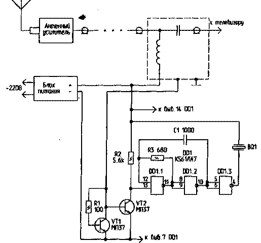
Diagram of the device shown in the figure. It consists of a key on the transistors VT1 and VT2 and tone generator on the chip DD1. The device is included in the gap minus the power circuit of the antenna amplifier and operates as follows. When you turn on the power supply network of the transistor VT1, through resistor R1, is opened and voltage is supplied to the antenna amplifier. The current flowing through the amplifier creates a voltage drop sufficient to open the transistor VT2. Thus the voltage on the collector is less than 1 V, which is perceived by the input of the element DD1.1 as a logical "On" and the generator is not working.
When breakage or disconnecting the antenna cable supply voltage is removed from the transistor VT1. Transistor VT2 is closed. Its collector voltage appears logical "1". In this case, the generator turns on and sounds the alarm.
The tone generator is made under the scheme of the multivibrator of two logical elements DD1.1 and DD1.2. The element DD1.3 is a buffer. The generator is loaded on the piezoelectric emitter from an electronic clock. The design of the device allows you to use any low-power germanium transistor structure p-p-p, with open lower resistance of the junction, the collector-emitter and having a lower bias voltage. Use patterns transistors p-n-p, but that would require changing the polarity of the enable device in the supply circuit of the antenna amplifier and the use of additional inverter before DD1.1.
Chip DD1 can be substituted from the series C or 564. Resistors and capacitors may be of any type, preferably small. The device is mounted in the housing of the power supply of antenna amplifier. In this case the piezoelectric emitter is mounted on the outside and glued to the side wall of the housing through the thin foam gasket.
Check the operation of the device is as follows.
Turn on the power supply of antenna amplifier in the network. From antenna connector leading to the TV, disconnect the Central core of the cable (it is screwed with a screw). This should sound alarm tone. If necessary, the frequency of the tone can be changed by selection of the capacitance C1.
This watchdog can be used to protect against theft of satellite antennas and other products, the power which is produced by a two-wire line.
Author: S. rybczynski, Valdai-5, Novgorod region; Publication: N. Bolshakov, rf.atnn.ru