


")

We hope that You are already familiar with the design standard J-antenna, so will not delve into unnecessary details. The proposed antenna is a variation of the J-antenna and can more successfully apply for one, two, three, or more bands. Feed of this antenna can be supplied from separate cables for each band, and one cable, though the first option is the most preferred.
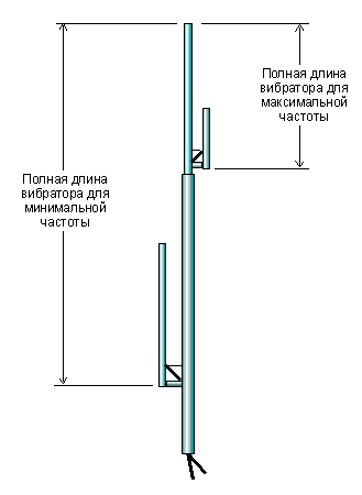
In antenna design has no guile, just do not forget that the total length of the antenna is determined by the lowest operating frequency. In other words, if You use the antenna on 144, 430, 900 MHz, the total length will match the length of the antenna 2 meter range, i.e. about 150 cm.
Coaxial cables are passed inside the Central pin to the corresponding elements. Between antenna elements are T-shaped joints. The challenge in designing antennas is that the more bands You use, the harder it is to ensure the uniformity of the SWR on all bands.
Table of the dimensions of the antenna for some ranges Frequency 52 MHz 146 MHz 223.5 MHz 435 MHz 912 MHz 912 MHz The diameter of the vibrator (mm) 25 18 12 12 9 9 The loop length (mm) 1367 484 316 161 75 54 Total length (mm) 4098 1452 948 485 227 162 The distance between the vibrator and ribbon cable (mm) 125 50 25 18 12 6 Connection cable (mm) 150 60 37 25 18 12
For best results, first fabricate the high-frequency vibrator, for example for the range of 435 MHz. The vibrator is made of copper tube of diameter of 9 mm, a matching line - copper 6-mm tube. Of course, the final product will be in the form of a "J". Now produce elements the following range, for example on 223.5 MHz, adding up to the T-connector, which is the base attachment of the 435 MHz antenna. We used a 12 mm tube vertical radiator and 12 mm for cable of this section. Now fabricate 146 MHz antenna, do not forget that the total length of the antenna is the lowest frequency you will be using. We use 18 mm tube vertical radiator and 12 mm for loop. The loop should be parallel to the vertical emitter, but it can be on either side about a vertical axis. We prefer to place them on pairwise opposite sides, but you can do them all on one side if you want. Finally the appearance of this antenna resembles a cactus, whence its name.
Last note: If you are using a 12 mm pipe for whole structure, 2-meter cable add 6 mm to the length so that you can make the adjustment. Fabricated antenna after the configuration is not worse SWR of 1.2 to 1 at all ranges, provided that for each range, using the mains cable.
Solder all the elements before installing coaxial cable. To install the cables and drill holes 6 mm in diameter at the top part of the horizontal element of the T-connector closer to the vertical part (in the corner) and push the cables through them.
Enjoy the result! And one more thing: in the beginning, until You've mastered the manufacture of such antenna, do not make more than three bands on one vibrator.
Use one cable to power the multi-band antenna
(Unfortunately, in English).
Single Coax Feed to Multi-Band Copper Cactus Antenna.
There are three connection possibilities to feed the multi-band copper cactus antenna with a single feedline or coax. However, it is imperative that you use the proper coax for the highest band of operation, RG58 just won't cut it and even RG8 in lengths longer than 25 feet is marginal in operation 440.
For all single coax feeding methods, the antenna will require re-tuning to obtain the lowest SWR for each band. This is accomplished by installing in the pipe cap of the tuning stub on each band of operation a brass machine screw of at least 2 inches in length vertical out of the cap.
The first and simplest connection method, albeit the hardest to tune, requires that you place a shorting wire on all but the lowest band of operation. If you are building your antenna from the N0ZOI (now KG0ZP) plans for "The Copper Cactus Antenna" and for example building a tri-bander for the frequencies of 144, 220 & 440 MHz, the shorting wires should be placed between the normal connect points for the shield and center conductor of each band. The 440 band shorting wire should be placed exactly 1 inch above the top of the horizontal pipe of the 440 tuning stub, the 220 band shorting wire should be placed exactly 1-1/2 inches above the horizontal pipe of the 220 tuning stub and your coax suitable for 440 operation should be connected exactly 2-1/4 inches above the horizontal pipe of the 144 tuning stub with the center of the coax going to the main vertical and the shield to the tuning stub (this is just the reverse of the connections shown on the plans and in the methods below), keeping the center conductor length as short as possible. For best results, tune the antenna from the highest band to the lowest, however, using the shorting method does create quite a bit of interaction.
The second method is easier to tune than the first method, but does require placing a 1/4 or 1/2 wavelength matching sections for all the bands of operation. If you are building a dual band antenna, the use of a T-Connector simplifies the project. Please bear in mind that you cannot use a 1/4 wavelength matching section on one band and a 1/2 wavelength matching section on another band, plus each band of operation requires the use of a matching section, including your lowest band of operation. Unfortunately, the connections will be inside the vertical section, a feat not easy to accomplish, but it does make tune-up much faster and easier than the shorting strap method shown above. The center connector of the coax matching sections is affixed to the tuning stub and the shield to the vertical section, keeping the center conductor lead length as short as possible.
The third method requires no antenna, re-tuning from the specifications given on the plans and random length pieces of coax may be used. However, a relay switching assembly must be constructed inside a weathertight enclosure or the use of a duplexer for dual-band operation or tri-plexer for tri-band operation can be utilized. As above, the center conductor of the coax goes to the tuning stub and the shield to the vertical. I will note that I have used random length coax, without *-plexers or relay assemblies, however, this method worked on only three of five duplicate antennas using the same random length pieces of coax on each. Each band showed an SWR of less than 1.025 to 1 until connected together, then two of the antennas showed an SWR of over 3 to 1 and three antennas were less than 1.8 to 1 across all bands without re-tuning. A little re-tuning brought the SWR down to below 1.2 to 1 on two of the antennas, but we could not acheive anything lower than the original 1.8 to 1 on the third. So if you use random length coax and no relays or *-plexers, good luck.
NOTE: The connect distance above the horizontal member on each band is selected for an impedance of around 50 ohms, moving the connect point up or down from this set point can and will increase the impedance as high as 650 ohms within a distance of 1/2 inch either side of the established proper connect point.
Author: Gary, KG0ZP; Publication: N. Bolshakov, rf.atnn.ru