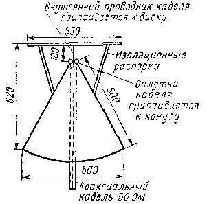
Compared with coaxial antenna disco-cone antenna with circular radiation pattern and the same way of eating, has much greater bandwidth. Compared to conventional dipole the gain of this antenna is equal to -3dB. This decrease in gain should not come as a surprise, since disco-conical antenna has the correct directional pattern with a very large bandwidth. Design disco-conical antenna shown in Fig. 11-40, subject to specified dimensions and direct power over a coaxial cable with a characteristic impedance of 60 Ohms has a band transmission from 85 MHz to 500 MHz.

Fig.1
The cone is made in the form of a horn from a sheet of copper or any other material that is easy to solder. The power cable is inside the cone and its outer braid is soldered to the cone, but the refined cut the inner strands with a length of 100 mm to a metal disc. The disc is held in a horizontal position by insulating supports.
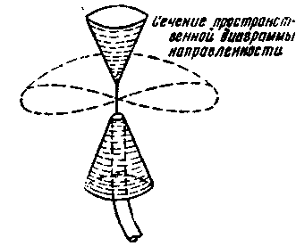
For the establishment of distant QSOs in the range of 144 - 146 MHz and especially at 420-425 MHz it is necessary to concentrate the radiation of electromagnetic energy in the form of a narrow beam and to direct it as close as possible to the horizon. It also needs to be able to establish radio communications with correspondents located in various directions from the radio with a fixed antenna. For this case the antenna must be in the vertical plane the radiation pattern in the form of elongated eight, and in a landscape in the form of a circle. A similar diagram can be obtained in the performance of the biconical antenna (Fig. 2), representing two metal cone, to one of which the affiliated middle lived cable and the other as his braid. The disadvantage of this antenna is the need for symmetric excitation.

Fig.2
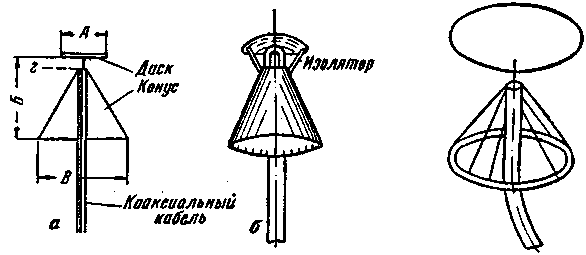
Broadband biconical discolora antenna (Fig. 3), in which the role of the upper cone performs the drive does not require symmetric excitation. In table.1 shows the dimensions discobonus antenna, designed for operation in the Amateur bands.
Table 1
Operating frequency range, MHz
Dimensions, mm
A
B
In
g
30-90
1500
1 820
P
40
90-450
550
685
555
30
900-1 800
80
125
85
10
For the selected antenna work is desirable to maintain in the field the lowest operating frequency, since the increase of the operating frequency, the angle between the direction of maximum radiation and the horizon increases. The power antenna is a cable with a characteristic impedance of about 60 - 70 Ohm no matching devices. The drive is isolated from the cone, which may be grounded. For operation in the range of 38 to 40 MHz cone and disc are made of pins with a diameter of 3 to 5 mm (Fig.4). The maximum distance between the pins should not exceed 0.05 L.

Fig.3,4
Literature:
1. K. Rothammel. Antenna. Moscow "Energy". 1979.
2. F. burdeyny, etc. Guide the shortwave. Because in DOSAAF, Moscow. 1959.
Publication: N. Bolshakov, rf.atnn.ru


