


")

If ham two single-band antenna (144 and 430 MHz), but dual band radio, antenna can be connected to a single cable, installing on the roof of the crossover. A similar filter is suitable for solving the inverse problem - the summation of the input signals from two single-band radio stations when operating on a single dual band antenna.
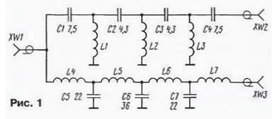
Diagram of the device shown in Fig. 1. It consists of a high-pass filter with the cut-off frequency of 350 MHz and low-pass filter with a cutoff frequency of 200 MHz. HPF assembles the elements of the L1 - L3C1-C4, and the LPF - on elements L4 - L7C5-C7. Interchange between nests and XW2 XW3 - not less than 40 dB, and the loss in bandwidth filters are a fraction of a decibel. In the 144 MHz band, the device provides additional suppression of harmonics of the main signal 20…30 dB (100… 1000 once in power).
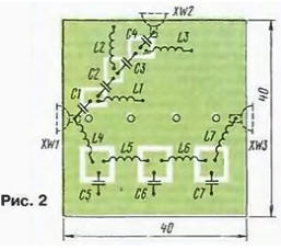
Details of the antenna filter is placed on the circuit Board from double-sided foil fiberglass, a sketch of which is shown in Fig. 2. Second the left side of the Board metallized and connected in circuit with metallization first side strips of foil. In addition, the parties are to be interconnected segments of the conductors are passed through holes in the circuit Board. Between LPF and HPF charge sealed shielding baffle.
The device can be applied to the capacitors types CD. K10-17. All coils are wound wire sew-2 0,9 mandrel with a diameter of 4 mm and contain: L1 - L33 - 1.5 turns with a step of 2 mm, L4 and L7 - 3.5 coils with the winding length of 6 mm. L5 and L6 - 4.5 a coil wound around a coil to a coil. The length of the findings from the coils - 7…8 mm.
All connections and terminals of the capacitor should be of a minimum length. One of conclusions elements L4, L7, C1, C4 solder directly to the jacks.
Charge is placed in a metal case (or casing, welded of foil fiberglass), the walls of which are installed high frequency socket XW1 - XW3.
Establishing an antenna filter is in principle not required, but installation should be sure to verify the settings to be sure of the efficiency device. To make it easier in a panoramic indicator frequency response or by using generator and an RF voltmeter.
When working on two separate antenna filter is placed on the roof. Cable connect to the socket XW1, antenna 144 MHz band - slot XW3, and the antenna band 430 MHz - slot XW2. If using two radios, the filter come near them, and instead of antennas to jacks XW2, XW3 connect the outputs radio stations corresponding range.
When the device is placed on the roof should cost and elements to cover varnish, providing a seal body.
Author: I. Nechaev (UA3WIA)