The development of local FM networks in the 144 MHz band and the increasing distribution of repeaters has led to increased interest in Amateur radio by Omni-directional antennas with vertical polarization. In addition to the classical quarter-wave pin (GP) is very often used antenna with the length of the radiator 5/8 L. In such an antenna radiation pattern in the vertical plane pinned to the ground, which increases the communication range. Moreover, compared with GP antenna 5/8L has a gain of 3 dB.
In the Korean journal Monthly KARL (1996, April, p. 55-56) published a brief description УSW antenna, which is a common-emitter composed of two antennas 5/8L.
From General considerations it can be argued that such an antenna with acceptable dimensions (overall height with mast about 3 m) has even more gain than a single 5/8L compared to GP. Described version of the antenna used by the U.S. Navy (USN STAR GP ANTENNA VHF) and has a bandwidth of 120...158 MHz with VSWR less than 1.3.

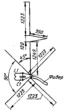
Schematically the antenna shown in Fig. 1. The top of the vertical emitter is fed through the phase-shifting line. At an angle of 45" to the bottom of the vertical emitter connected two additional emitter, which expand the working bandwidth. Two counterweight also located at an angle of 45° to the vertical emitters and have a length of about 5/8L. The coordination element of the antenna with 50-Ohm feeder - circuit L1C1.
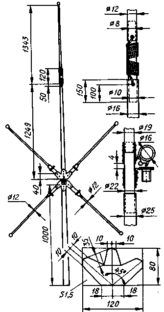
The design of the antenna shown in Fig. 2. The upper and lower emitters are connected by a dielectric insert, which is wound phase-shifting line. Phase-shifting line is made of copper wire in isolation. The wire diameter of the article is not specified, but from General considerations it needs to be as large as possible (if only the line fit on the frame). Its triangular shape allows it to be wound on a dielectric frame turn to turn. Between the lower end of the lower radiator and a metal pole with a length of 1 m is also a dielectric insert (counterweights mast is not electrically connected).

Balances and dielectric insert sandwiched between three parts (see Fig. 2). Additional lower emitters and integral counterweights. To three fold detail attached the pipe pieces with clips, which include emitters and balances, which are made of pipes of smaller diameter. This gives you the ability to change their length in the process of tuning the antenna. Coil frameless. It is made of bare copper wires with a diameter of 1.5 mm and has two turns with an inner diameter of 16 mm. the capacitance of the capacitor C1 5 10... pF.
Since the antenna is factory-built, vertical radiators have a variable diameter. At the bottom of the pipe he, in particular, varies from 19 to 16 mm (see Fig. 2). In Amateur designs can certainly use conventional pipe with constant diameter.
Publication: N. Bolshakov, rf.atnn.ru


