


")

In the magazine "Radio" is already explained on the harmonization of small antennas ("Radio", 1996, No. 4). The article describes a variant of the extended antenna for portable radios.
General view of the antenna shown in Fig. 1.
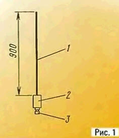
Here 1 - pin is made of elastic steel wire (piano) with a diameter of 2…2.4 mm; 2 - device settings and coordination; 3 - pin connector part corresponding to the antenna Jack radio station.
Schematic diagram of the matching device depicted in Fig. 2.
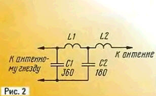
P-loop L1C1C2 transforms the resistance of the antenna system 50 Ohms. and lengthening the coil L2 lowers the resonant frequency of the antenna system to 27 MHz.
Coil L1 is frameless. Her wound wire sew-2 0,8 mandrel diameter 6 mm Number of turns is 9. and the winding length of -12 mm. Coil L2. containing 40 of turns is wound tightly in a number of wire sew-2 0.41 on the frame with a diameter of 6 mm. In the quality of the frame you can use high voltage resistor type C3-14-0,01. Capacitors C1 and C2 can be types km, KG, or CSR.
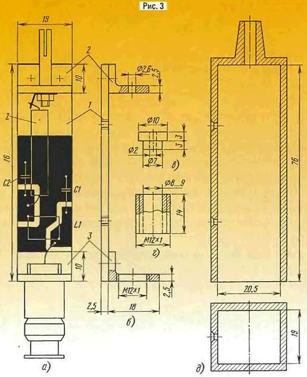
All elements are mounted on a single-sided PCB 1 out of fiberglass 2.5 mm thick (Fig. 3. and. b). The upper and lower ends riveted duralumin parts 2 and 3. On the corner 2 attach the socket from the connector type SR right diameter, and area 3 - connector type SR-50-PV. in which the connection element is with coaxial cable replaced glued two washers liner high impact polystyrene (Fig. 3. in) and fixing it in the plug housing short tube (Fig. 3. g). Projecting from the plug end of the tube is screwed into the corresponding hole of area 3. The Central conclusion of the connector solder short guide. To avoid damage to the coils and capacitors for additional building slot antenna pin printed circuit Board is placed in the box (pull top), made from high impact polystyrene sheet thickness of 2…3 mm (Fig. 3. d). The box is fastened to the PCB with two screws (thread - in Board).
The proper configuration of the antenna can be checked by turning between the antenna and radio SWR meter (preferably small size): the CWS must achieve a minimum range of operating frequencies. If this minimum is shifted to the area of lower or higher frequencies (in multi-channel radio stations it is easy to check), the number of turns of the coil L2, respectively, reduce or increase.
On the SWR of the antenna affects the setting of a P-loop. Her precise, shifting-pushing the turns of the coil L1. Experience shows that these procedures in the middle of the range operating frequencies easy to reach the CWS. smaller 1.1. The bandwidth of the antenna in the level of VSWR of 1.5 is not less than 1.2 MHz.
As demonstrated in field tests, performed on radio station Dragon SY-101, the effectiveness of the described antenna, compared with the staffing, was 11 dB. what approximately corresponds to a twofold increase in the communication range. So significant the effect is due to inaccurate adjustment (alignment) of the standard antennas. So. the inclusion of "spirally" Dragon via a device similar to that described above, is possible to increase the signal level at the point of admission to 4 dB. However, it is C1=300 pF, C2=180 pF; the length of the winding coils L1 - mm; coil L2 - frameless, contains 15 turns is wound tightly in a number of wire sew-2 0.8 mandrel with a diameter of 3.3 mm.
Author: Yu. Vinogradov, Moscow