


")

In CBS the range of the most widely antennas with vertical polarization. This is because CB radios are widely used for communication with mobile objects, and the car is very difficult to place effective antenna horizontal polarization. For the same reason as the base selects the antenna with circular radiation pattern in the horizontal plane, working equally well in either direction.
GP with a length of l/4
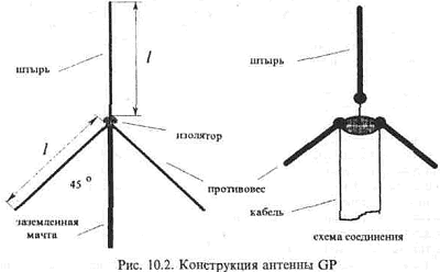
The most widely used in this group received antenna type "Ground Plane", or abbreviated to "GP", shown in Fig. 10.2.
The whip antenna has a design, convenient for placement on the roof of the building and on the car. It is simple and, at the same time, is quite effective. The length of the pins (l/4) for operation in the range of 27 MHz depends on the diameter of the tubes and are listed in table.1
Table 1. The length of the antenna elements GP

For normal operation of the antenna it is supplied with three counterweights that can be performed from the tube or antenna cord. The length of the counterweight is selected equal to, or 2.5% more 2/4l. For the CB range, you can take it equal to 275 cm Input impedance of the antenna depends on the angle between the counterweight and mast: the smaller this angle (counterweights pinned to the mast), the greater the resistance. To obtain the input impedance of 50 Ohms, the angle is chosen equal to 30-45 degrees. Directivity in the vertical plane has a maximum angle of 30 degrees to the horizon. The antenna gain is approximately equal to the gain vertical half-wave dipole. Best operation is provided when the height of the mast about 6 M.
This antenna is most of all the broadband options GP. If the minimum SWR of the antenna is slightly above or below the channel frequency of 20 mesh, the length of the pin is necessary to accordingly increase or decrease. After tuning the antenna to resonance minimum SWR at the average frequency is achieved by changing the installation angle of the balances.
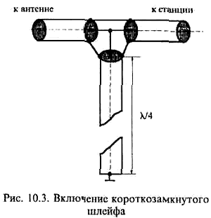
The disadvantage of this design is the lack of a pin connection with a mast, which requires additional lightning protection measures and protection against static electricity. The simplest method of protection is the use of a short-circuited loop of cable of length l/4, connected to the feeder with the help of tee. The cable provides a connection of the Central conductor of the feeder with a grounded braid DC and does not affect the harmonization of the antenna. The scheme of connection of the flat cable shown in Fig. 3
The loop length is calculated taking into account the velocity factor of the cable used and is about 2 M.
GP with length l/2
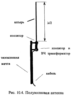
In Fig. 10.4 shows the design of a half-wave GP antenna of length l/2. Compared to the above antenna it has twice the length of the pin that imposes requirements on the provision of wind strength. The antenna needs no counterweights, the role of which performs the mast, and its directivity in the vertical plane stronger pressed against the horizon, which improves the radio with remote correspondents. Since the antenna has a high input impedance, the cable is connected thereto through a matching high frequency transformer. The base of the probe is connected to a grounded mast via a matching transformer that automatically solves problems of lightning protection and static. The gain of the antenna compared to a half wave dipole is about 4 dB.
Typical data matching transformer: The diameter of the frame - 30mm The diameter of the wire (sew-2) 1mm The number of turns - 6 Withdrawal from 1.5 - revolution counting from (cold) grounded output coil The cable connects Central residential to the challenge. The leaf antenna is connected to "hot" the output of the coil. GP with a length of 5/8l
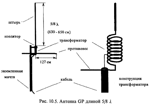
Most effective for long-haul communication is a GP with a length of 5/8l. Its construction is shown in Fig. 10.5. It is slightly longer half-wave antenna and the feeder cable is connected to the matching inductance, located at the base of the vibrator. This type of antenna requires the use of at least three counterweights length (0,1-0,2)l arranged in a horizontal plane. Antennas of this type scopolomine half-wave, therefore they require more careful tuning. The setting at medium frequency is provided by changing the length of the pin and adjusts the amount of the matching inductance. The desired input impedance is achieved by selecting the connection point of the cable to the matching coil. The gain of this antenna is 5-6 dB, high beam is angled 15 degrees to the horizon. Pin this design is also grounded to the mast through a matching coil.
Sample data matching the coil to the wave resistance of the cable 50 Ohm: the diameter of the cage 18 mm, the wire diameter is 1.5 mm, the number of turns - 22, the winding step of -2.5 mm, allotment - from the 9th round, counting from the grounded end of the coil.
Installing the antenna on the roof can greatly affect its performance. General recommendations are as follows:
- the base of the antenna it is desirable to have not less than 3 m from the plane of the roof;
- near the antenna should be free of metal objects and structures (such as television antennas, wires, etc.);
- to install the antenna preferably as high as possible;
- for normal operation the nearest station base CB antenna should not be located closer than 200 m.
The efficiency of the antenna for transmission, the higher the lower the ohmic losses in its elements. Therefore, the best material for the antenna elements are copper tube, however, an acceptable compromise can be considered the use of aluminum (duralumin) of the tubes (due to high specific weight and low strength of copper).
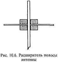
If you need to expand the bandwidth of the diameter of the tubes increase, or use a tube with a ribbed outer surface. Since the current flowing through the pin of the antenna, is reduced to its upper end, the diameter of the upper part of the pin can be reduced without deterioration of its parameters. One of the simplest means to increase bandwidth long whip antennas is the use of bushings with four whiskers with a length of about 100 mm and a diameter of 4-5 mm, fastened at the top of the pin (Fig. 10.6). Thus the resonant frequency of the antenna decreases and the length of the pin will have to be reduced. When operating the antenna at the transmission on it is leaking quite large currents, it is therefore necessary to provide a very good connection all the elements together and to take care of their protection from corrosion.
Currently on sale are CB antenna factory-built (Fig. 10.7), both domestic and imported, light, nicely finished. As the experience of their operation, in the compounds of elements, which are self-tapping screws, the wind quickly enough to lose electrical contact. More reliable is the design of the pins tie clips. Almost all versions of industrial antennas require additional sealing to prevent water entering the pipes, matching transformers, coils and termination, which leads to irreversible consequences.
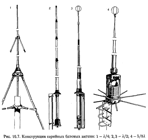
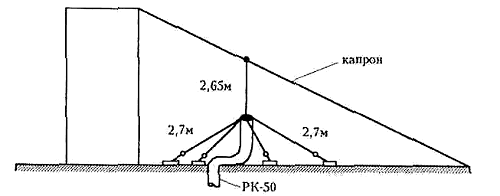
Fig. 10.8 GP Antenna without a mast
If Your roof is high enough, lift box, TV antenna or outbuilding with a height greater than 5 meters, antenna GP can be set using nylon rope-stretching (Fig. 10.8) without mast. In addition to the nylon cord and cable RK-50, it will take another 4 detention facility of any type. End of the cable length 2.7 m is released from the outer insulation and braid, braid rasplatitsja and braided into 4 approximately equal "pigtails". They are joined by the counterweights. The counterweights can be made of any of copper (in extreme cases, even aluminum) wire, which is screwed (or soldered) to "braids". Length balances should be 2.7 m. At the ends of the counterweights are fixed insulators which are attached to a wire or nylon the guys. The end is released from the outer part of the cable behind the plastic insulator is attached to a nylon cord so that it pulled off by gusts of wind. The counterweights are pulled apart evenly in a circle, delays are fixed on the roof (for example, attached to the bricks). Try the length of braces to be chosen so that between the wire counterweight and vertical angle was about 45°. The joints and the exit point of the cable braid is carefully sealed with plasticine to under braid is not exposed to water.
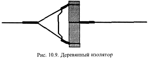
This antenna characteristics are fully consistent with the classic GP antenna of length l/4. Such an antenna is very convenient to install in the field between two trees, you only need to prepare in advance the cable and balances with braces, and as insulators at the ends of the counterweights will fit even a short dry sticks (see Fig. 10.9), since at a frequency of 27 MHz is a good insulator.
Literature
Publication: www.cxem.net