")

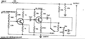
Here is the hum remover circuit diagram. “Hum” usually occured from live audio system, for example: input from microphone. Hum can be removed from an audio signal to get the maximum performance by mixing the actual hum with an antiphase hum in equal level. You can use any NPN transistor to support this circuit.
VR1 adjusted with VR2 until the hum is at minimum. SW1 may have to be changed over, then adjust VR2, is altered until the hum is removed.
This circuit is an active circuit that worked with 9-15V DC supply. Stabilized and regulated power supply is necessary for maximum performance.
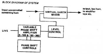
Block diagram of hum remover: