


")

Here is the circuit diagram of 100W audio amplifier which using power transistor BDW83D and BDW84D for the final amplification. It uses dual polarity power supply to work. Copyright belong to Smart Kit.
The circuit should be seen like this:
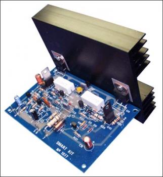
This is an exceptionally well designed amplifier, with a lot of power reserve, high fidelity, low distortion, good S/N ratio, high sensitivity, low consumption and full protection. Having all these almost ideal characteristics this amplifier is likely to become the basic building block of your future high fidelity system, or it can also become the element that will upgrade your existing system.
Schematic diagram:
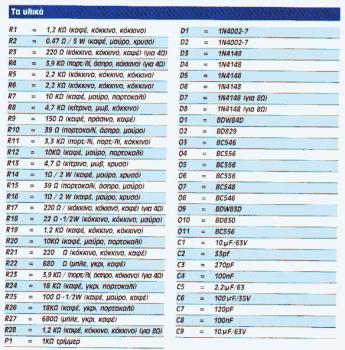
Component part list:
PCB Layout:
Component placement:
Technical Specifications:
Output power (f=1 KHz, d=0.5 %): 100 W in 8 ohm
Supply voltage: ……………. ?? 40 V
Quiescent current: …………. 50 mA
Maximum current: …………… 2.6 A
Sensitivity: . 600 mV
Frequency response: ………… 10-35000 Hz (-1 dB)
Distortion HD: …………….. 0.01 %
Intermodulation dist.: ……… 0.02 %
Signal/noise: 83 dBConstruction
Go to this page for detailed explanation.