


")

Scheme desulfating chargers offered by Samundri and L. Simeonova.
The charger is made but the scheme half-wave rectifier diode VI with parametric voltage (V2) and current amplifier (V3, V4). The signal light H1 is lit when plugged in the transformer. The average charging current of about 1.8 And is governed by the selection of resistor R3. The discharge current is set by resistor R1. The voltage on the secondary winding of the transformer is equal to 21 In (peak value 28 In). The battery voltage at the rated charging current is equal to 14 V. Therefore, the charging current of the battery occurs only when the amplitude of the output voltage of the current amplifier exceeds the battery voltage.
During one period of the alternating voltage is generated one pulse of charging current during the time Ti. The discharge of the battery occurs during the time TK= t. Therefore, the ammeter indicates the average value of the charging current equal to approximately one-third of the peak value of the total charge and discharge currents.
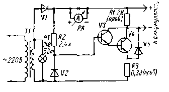
In the charger, you can use the transformer TC-200 from the TV. The secondary windings of both coils of the transformer is removed and wire sew-2 1.5 mm is wound a new coil, consisting of 74 turns (37 turns on each coil). The transistor V4 is mounted on the radiator with the effective surface area of about 200 sq cm
Details:
Diodes (type VI DA. DA, DA. D305, V2 one or two of the Zener diode connected in series DA, V5 D226 type: transistors V3 type CTA, V4 type CTA or CTA.
When setting up the charger should match the voltage on the base of the transistor V3. This voltage is removed from the arm (470 Ohm) connected in parallel with the Zener diode V2. In this case, the resistor R2 is chosen with a resistance of about 500 Ohms. The movement of contact arm making to the average value of the charging current was 1.8 rasselas
Publication: N. Bolshakov, rf.atnn.ru