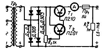
Fig.1
The resistor R2 to the output of the rectifier allows you to set the output voltage of the rectifier when the load is switched off. The transformer is assembled on the core section 6 cm2. The primary winding is designed for inclusion in the network with a voltage of 127 V (pins 1-2) or 220 (1-3) and contains 350+325 turns of wire sew 0,35, secondary - 45 turns of wire sew a 1.5. The transistor T1 is mounted on a metal heat sink, the surface area of the radiator must be at least 350 cm2. The surface is taken into account on both sides of the plate at a thickness of not less than 3 mm.
Author: B. Vasiliev
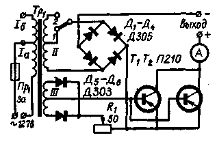
The circuit shown in Fig. 2, differs from the previous one, to increase the maximum current to about 10 transistors T1 and T2 connected in parallel. The offset to the base of transistors, the change of which is regulated charging current is removed from the rectifier diodes made on the D5 - D6. When charging 6-volt batteries, the switch is set to 1, 12-volt - in position 2.

Fig.2
Winding of the transformer contain the following number of turns: la - 328 turns sew 0,85; 1B - 233-loop sew 0,63; II - 41+41 round sew 1,87; III - 7+7 turns sew 0,63. Core - USH 55.
Author: A. Varlashkin; Publication: N. Bolshakov, rf.atnn.ru


