


")

The advantage of electronic stabilization system on-Board voltage before Electromechanical is a high reliability, fast and convenient installation of the generator voltage, in the absence of the need for any preventive operations associated with operation of the stabilizer. On the cars electronic stabilizers used for a relatively long time, and now they are to equip and motorcycles. One of such devices is described in this article.
The stabilizer is designed for installation on heavy motorcycles Dnepr and Ural, which source of electricity is a synchronous generator G 424, stabilizes voltage serial Electromechanical relay controller RRSS. The vehicle voltage is 12 V.
The described device is a proper stabilizer and node indicate the mode of operation of the generator.
The stabilizer is assembled on the basis of the device [1], which have become standard. The measuring element is VD1, VT1, and amplifying - VT2, VT3 (see diagram). Diode VD2 is used to protect transistor VT3 from high-voltage pulses of self-induction winding created by the rapid closing of the transistor.
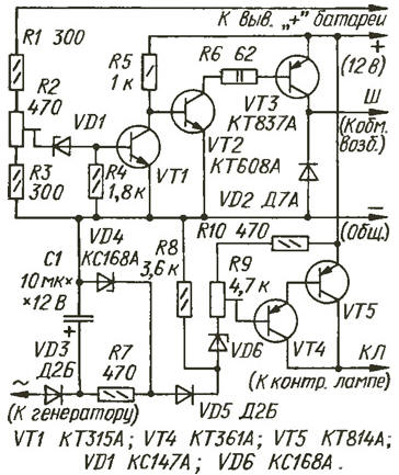
The node display consists of a transistor switch amplifier current VT4VT5, loaded indicator lamp TC (not shown), threshold the device collected on elements R8-R10, VD6, detector over voltage R7VD4VD5 and rectifier VD3 with a smoothing capacitor C1.
The relative lack of stabilizer is that when you reduce battery voltage battery is lower than 7 In the control lamp will not burn. But this battery, nominal voltage 12 In which is possible only in the case her accidental discharge that could lead to sulfation.
Until the alternator voltage is small, the transistor VT1 is closed, a VT2 and VT3 are open and through the excitation winding of the generator current flows, causing the voltage of the generator increases. Once it reaches the nominal level, opens the Zener diode VD1. This will lead to the opening of the transistor VT1, closing transistors VT2, VT3 and the cessation of current through the excitation winding. As a result the output voltage of the generator begins to decrease.
Once it is reduced to the value at which closes the Zener diode VD1, transistor VT1 is closed, a VT2 and VT3 opens, renewing the current through the coil the excitation of the generator, the voltage at the output will increase again. The described processes are repeated, and the on-Board voltage varies in a very narrow the range around the nominal value, which is set trimpot resistor R2.
With the ignition on, but engine not running, the voltage applied to the Zener diode VD6 exceeds its voltage stabilization, therefore, composite transistor VT4VT5 opened, through the control lamp current flows. The voltage at the resistor R8 is about 5 V.
As soon as the engine starts, there will be an alternating voltage on the clamp "~" (the output of the oscillator phase) is about 5.5 relative to the housing In motorcycle [2]. After rectifying diode VD3 and the smoothing capacitor C1 it will be applied to the resistor R8, the voltage of the Zener diode VD6 will be lower voltage stabilization, it will close, so close and composite transistor VT4VT5 - the warning light goes out.
If the alternator voltage will increase and will exceed the value of approximately 14 In, opens the Zener diode VD4 and the voltage at the anode of the diode VD5 more will not grow. The same voltage at pin +12 V will increase in will open a Zener diode VD6 followed by a composite transistor VT4VT5. Diode VD5 prevents shunting of the resistor R8 and Zener diode VD4 working in the modes. In those cases, when the alarm of the excessive voltage is not required, elements R7, VD4, VD5 you want to exclude.
The stabilizer is not critical to the parameters of the components. Transistors VT1, VT4 can replace any low-power appropriate structure, VT2 - average power, VT3, VT5 - powerful, if only their static current transfer ratio was more 10. Transistors VT3 and VT5 must be installed on the heat sinks.
The Zener diode VD1 may be at a voltage in the range of 3…10 V, but preferably with a negative temperature coefficient of voltage stabilization, which will provide a slight increase in voltage of the generator when the temperature drops. Zener XA (VD4, VD6) can be replaced by XV.
Fixed resistors - MLT, trimming any. The capacitor C1 is any the oxide. The diode D2B (VD3, VD5) can be replaced by any low-power direct-current not less than 10 mA, and DA (VD2) - any of the series D7, D226, CD.
Correctly assembled device does not require the establishment of, you only need to install the rated voltage of the generator and the voltage of the node alarm over-voltage generator.
To do this, connect the voltmeter directly to the battery pack. When the engine is running to set the voltage generator resistor R2 on around 13,7 V. to Ensure that the significant increase in turnover the engine does not exceed 14 V.
Further, closing the terminals " + " and "W" and increasing the rotational speed of a crankshaft the motor so that the voltage becomes equal to 14.5, the resistor R9 to install the faint illumination of the warning lamp. To disconnect the terminals "+" and "W" and make sure that at a voltage of 14 In the lamp goes out completely, and if you increase the voltage above 14,5 shines In full intensity.
The stabilizer is mounted and installed on a motorcycle "Ural" in a separate box next to the relay controller. Operation of this equipment in a few years showed its reliable and stable operation. Additional the adjustment arose.
Literature
Author: A. old believers, Vologda