


")

Moving in reverse, the driver can't see a certain zone road space. This zone has a length of two meters, and it can be people or animals, as well as items that represent a hindrance for movement. The achievements of modern technology allow us to create a special the device for review specified space and driver information in if on the road car meet any objects. The most optimally this task is solved with a pulsed acoustic location. Known successful attempts to build such devices (see, for example, the book Whitefish X., Mizutani S. "Introduction to automotive electronics". - M.: Mir, 1989). However due to the complexity and high cost of these locators has not yet received a wide application.
Acoustic locator, we offer readers made on the basis of microcontroller Z8. It is simple, easy to repeat the hams. When the corresponding modification program and design it can be used in an indispensable assistant for the blind, devices, protection of premises, portable sonar anglers, non-contact level indicator fluid, etc.
Schematic diagram of the locator shown in Fig. 1. It is based on a microcontroller (MK) Z86E0208PSC (DD1).
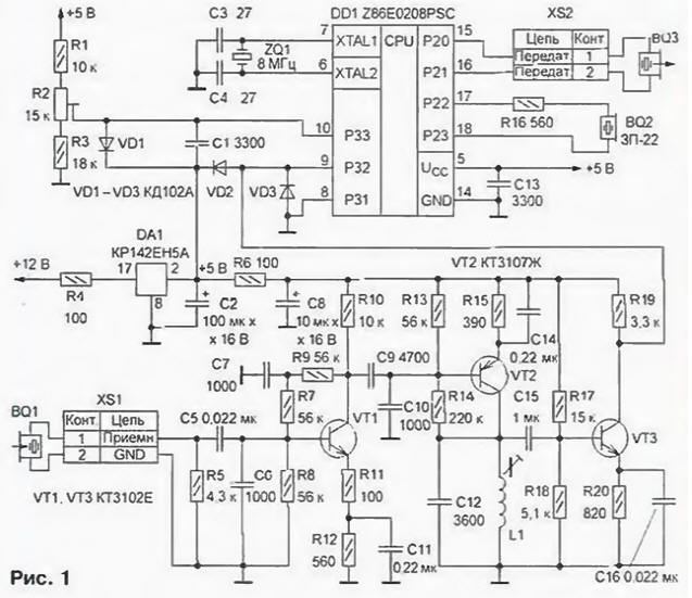
External vimasuma chain MK consists of quartz resonator ZQ1 at a frequency of 8 MHz and a capacitor C3. C4. Ultrasonic the emitter BQ3 connected directly to the pins of port P2 MK. The scope the exciting voltage at the input of the emitter is equal to 10 V. packet duration pulses of 1 MS. The reflected signal, as adopted by the ultrasonic receiver BQ 1, is input to a three-stage resonance amplifier, made in transistors VT1-VT3. With its output signal with a DC component In 2.5 served on neinfectioase input (P32) internal comparator MK. On the inverting input of the comparator (RSS) comes exemplary voltage 2.7 V to divider R1R3. that ensures the selection of the useful echo signal on the level of received interference. The reference voltage circuit is additionally protected from interference limiting diode VD1 and the capacitor C1. Diodes VD2 and VD3 limit the instantaneous value of the reflected signal levels 0 and 5 V. Sound signal warning the driver about the presence of obstacles in the invisible area, is formed by the piezo oscillator BQ2. connected through a resistor R16 directly to the pins of port P2 MK.
Powered locator voltage of 12 V ± 2.5 V from the target signal reversing lights car. DA1 chip stabilizes the supply voltage level is 5V, necessary for normal work of the MC. In the power supply circuit device is installed a filter consisting of capacitors C2, C8, C13 and resistor R6.
The principle of operation of the locator based on the emission of the ultrasonic pulse packet frequency and subsequent reception of the reflected obstacle signal. The time from the moment radiation to the moment of reception of the reflected signal is directly proportional to the distance to the object. Depending on the distance locator forms one of two warning beeps: if it is less than 1 m, are generated frequent the tone of the parcel, if from 1 to 2 m - rare. At a distance of more than 2 m sound the signal is absent. The waiting time of the reflected signal is 60 MS, then radiates this bundle of impulses and the process repeats.
In more detail the operation of the device explains the graph [1], shown in Fig. 2 He includes four tops - state: SEND) - formation ultrasonic pulse packet; PRESS (SUPPRESSION) of the suppression of poslesvecheniya emitter; WAIT - waiting for the reflected signal and COUNT (CALCULATION) - the calculation of the distance to the object.
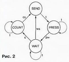
The transitions between the States shown by the arcs of the graph are caused by the following direct (indicated by a single letter) and indirect (two letters in accordance with transition) event: t (timer - timer) - timer MK, C (comparator comparator) - triggering of the comparator MC, ws (wait - send) - the end expectations reflected signal, cs (count - send) - end computing the distance to the object and pw (press - wait) - the end of time suppress.
When the power is automatically reset device and initializes the state of the SEND. The main function of this state - the resolution the formation of the ultrasonic burst pulse duration of 1 MS. Actuating the timer MK puts the device in the condition of the PRESS, in which it does not respond to adopted by the reflected signal. The duration of stay in this state is determined by the number of times the timer has fired, which you can modify according from the type of the ultrasonic transducer. At the end of the countdown time suppressing another timer enables the unit to the WAIT state.
In the WAIT state locator awaiting the arrival of the useful echo signal, which triggers the comparator MK. remembering the time from sending to receiving signal from the switch to the COUNT. The process of counting time in the WAIT state is synchronized by timer MK every millisecond. If after 60 MS in this state, the comparator MK doesn't work, the device again a status in the SEND. Upon actuation of the comparator goes under the state COUNT.
Able COUNT the locator continues to count the time interval of 60 MS. Then on the basis of the previously fixed time from the moment the parcel until the moment of receiving signal is calculated the distance to the object. In accordance with the result the calculation device controls the sound signal with the required interval "signal-pause". Upon completion of calculations it goes into the SEND. Further the cycle of operation is repeated In the locator, you can use any small ceramic and oxide capacitors. Coil L1 is wound on a single section unified frame with diameter of 8 mm and a length of the section of the winding 7 mm. Podstroechnik - ferrite (N) diameter of 2.8 and a length of 12 mm Reel contains 860 turns wound round wire PEL 0.15 (4.4 inductance mH). Resistor R2 - SP5-2, or any other small podstrony multi-turn. Piezoelectric sound emitter BQ2 - RFP-22 or similar. Transistors VT1. VT3 - any of a series of KT3102. VT2 - any of a series of CT.
The ultrasonic transducer BQ3 and receiver BQ 1 are identical. In the author's version used ultrasonic transducers commercially available from security devices "Echo 2", you can use any suitable piezoceramic transducers, including improvised, with the same operating frequencies in the range 36…38 kHz [2]. For their connection applied import connector DJK (on the Board establish their sockets DJK-2MR, and connection cables supply plugs DJK-2F).
Codes of the firmware ROM MK are given in the table. Much of the code is 242 bytes in size.
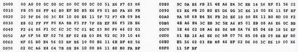
(click to enlarge)
Structurally, the locator consists of an electronic unit and the same design emitter and receiver Parts of the electronic unit mounted on the circuit Board from foiled fiberglass in accordance with Fig. 3.
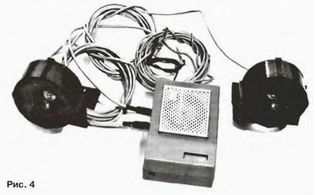
Board is placed in plastic case from radiokonstruktor "intercom" production JSC "Novgorod machine-building plant". The appearance of the locator in the collection shown in Fig. 4.
To reduce the acoustic impact of the ultrasonic emitter on the radio acoustic paths are in the form of horns. Horn, in addition, coordinate relatively high total acoustic impedance Converter with fairly low resistance loads, i.e. air pollution (3). The most effective exponential horn, the cross-sectional area which changed according to the law S = S0em , where S is the cross sectional area of the horn distance x from the transmitter, S0 is the area of the inlet horn (if x = 0), i.e. the area of the transducer surface, m is the coefficient of expansion the horn, which depends on the operating frequency (35 kHz t = 0.17 mm-1).
At home easiest way to make a horn whose cross-section is circular. Knowing that the area of a circle is equal to πD2/4, calculate the diameter the horn according to the above equation at different distances x from the transducer (x you can limit the size of 15…20 mm). Then the resulting values imps on paper, the longitudinal profile of the horn and on it make a template from a dense cardboard or tin. The horns do all of the template from the solid Styrofoam. The surface of the horns ink to give them the best acoustic properties. For protection from inclement weather the horns are placed in protective covers are provided with brackets for mounting on the rear bumper car. As skirts convenient to use plastic crossover boxes wiring. The brackets are made of sheet steel. Slit between the housing and the mouthpiece is filled with epoxy resin, and the entire structure is covered in several layers of weather-resistant synthetic enamel.
Establishing device start with checking the installation on the reliability of connections and no short circuits. Before installing the MC is advisable to check the work voltage regulator and amplifier of the ultrasonic signal. For this connect power and measure the voltage at pin 5 panel MK. It should be in the range of 5 ± 0.3 V. Then measure the DC voltage at pin 9 panel MK (2.5 V ± 10%) I. connecting a voltmeter to pin 10. set a trimming resistor R2, the voltage at 0.2 0.3…more first. Further, connecting the input of the oscilloscope to the output 9 of the panel MK and output at the input of the amplifier sine wave frequency of 37 kHz and an amplitude of 3 mV, watching on the screen oscilloscope signal with an amplitude of 4.5 V. the Tuning inductance coil L1 achieve maximum gain at a specified frequency.
After that, when the power is off set in the pre-panel programmed MK and connect the device to the transmitter and the receiver. If at power up, the device does not work, connect the input of the oscilloscope (with an input impedance of not less than 10 MW) to the output XTAL2 (pin 6) of the chip DD1 and test initiated whether the oscillator MK. The absence of oscillations sinusoidal frequency of 8 MHz indicates that the generator is not snowspeeders. In this case, you need to check the quartz resonator and ZQ1 capacitors C3 and C4.
When installed on the vehicle locator stir inside the cabin, and ultrasonic the converters on the rear bumper at a minimum distance of 0.6 m from one other. This distance ensures that the width of the working area locator equal to 2 m. Changing it. can be adjusted and the width of this zone.
Literature
Author: M. Gladstein, M. Balls