


")

Our industry produces a stroboscopic devices: car strobe STB-1 (Fig. 1) and the device Auto-spark" (Fig. 2), used to check and adjust the ignition timing on the car.
Know how important to the correct operation of the engine set the initial ignition timing as well as the serviceability of the centrifugal and vacuum controls ignition timing. Improper installation of the initial ignition timing only 2-3°, and the failure of regulators timing lead to loss of engine power, overheating, increased fuel consumption and, ultimately, to a reduction of the service life of the motor.
However, checking and adjusting the ignition timing is very delicate, time-consuming operation, which is not always available even for an experienced motorist. Stroboscopic devices allow to simplify this operation. With their help even inexperienced motorist may, within 5-10 min to check and adjust initial setting of the ignition timing, as well as to check the efficiency of centrifugal and vacuum regulators advance.
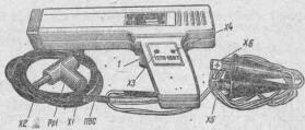
Fig.1. Appearance STB-1
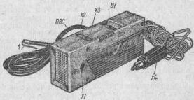
Fig.2. Appearance RENTALS-SPARK
The main element of stroboscopic device is a pulse instantaneous lamp, flashes which occur at the time of occurrence of sparks in the spark of the first cylinder of the engine. Consequently, the alignment markers marked on the flywheel or crankshaft pulley and other parts of the engine, rotating or moving synchronously with a crankshaft, when the strobe lighting them seem to be fixed. This allows you to observe the shift between the time of ignition and the time of passing the piston top dead center on all modes of engine operation, i.e. to control the accuracy of setting the initial angle of ignition to check the efficiency of centrifugal and vacuum regulators advance, and check the valves, camshaft and other engine parts.
Main technical data strobe devices STB-1 and Auto-spark" given in table. 1. As can be seen from table 1, automotive strobe STB-1 technical data far exceeds the device Auto-spark".
The name of the parameter
Automotive strobe, STB-1
The device Auto-spark"
Function
1. Checking and adjusting the ignition timing 2. Health check centrifugal and vacuum regulators ignition timing 3. Powered shavers constant voltage 127 V
1. Checking and adjusting the ignition timing 2. Powered shavers 127 V DC
Applicability (destination)
For all types of cars
Only for automobiles
The voltage, V
11 to 14
11 to 13
The maximum rotational speed of a crankshaft of the engine, rpm
3000
800
Allowable power consumption of the electric shaver, W
11
Not more than 7.0
The supply voltage of the electric shaver, In
From 115 to 140
From 112 to 138
Supply current, And
Not more than 1.5
Not more than 1.0
The life-h
50
Not specified
The temperature of the ambient air
25±10
Not specified
Relative humidity, %
85 at a temperature of +35°
Not specified
Weight, kg
0,7
0,8
First, the functions they perform. It allows not only to check initial setting of the ignition timing, but also to control the operation of centrifugal and vacuum regulators ignition timing. This is a quality strobe STB-1 is due to its good frequency properties that allow it to operate without reducing the brightness of the flashes with a frequency of up to 3000 rpm of the crankshaft of the engine. In the same device Auto-spark" the brightness of the flashes starts to decrease already at 700-800 rpm.
Secondly, the applicability of the strobe STB-1 is much broader than "Auto-spark" that is associated with the design of the device. As can be seen from Fig. 1 and 2, the strobe STB-1 is connected directly to the battery terminals with spring-type terminals KL1 L2 and K. type "crocodile", and the device Auto-sparkle has a coaxial plug X4, similar to the plug of the portable lamp' VAZ, in connection with which it can be connected only to those other cars. The dimensions of the handle of the device to "Auto-fire" are great, and it's uncomfortable to hold in your hand. In addition, the device emits a diffused light, and so I can see the marks, it should hold close to a rotating motor pulley. This is not only inconvenient, but also dangerous.
The strobe STB-1 is free from this drawback. Made in the form of a pistol with a lens that gives good focusing of the beam, it is convenient and safe in operation. A more powerful voltage Converter in the strobe STB-1 provides the ability to use virtually any collector with an electric razor.
The life of the strobe STB-1 is much larger than that of the device Auto-spark", which is associated with a resource of applied it stroboscopic lamp (SSH5).
The strobe STB-1 is connected to a spark plug of the first cylinder of the engine via a special adapter-spark PP1 providing virtually no" limited number of connections. The device is also "Auto-spark" is connected via a thin metallic conduit / (see Fig. 2), which usually breaks off after 10-15 connections.
Schematic diagram car strobe STB-1 is shown in Fig. 3. The device consists of a drive voltage for the transistors V1 and V2, silicon rectifier V4 block; limiting resistors R5 and R6; storage capacitors C2, C3, stroboscopic lamp H1; ignition circuit stroboscopic lamp, consisting of capacitors C4, C5 and arrester PP1; protective diode V3 and the switch S1 to switch the type of work "Razor" or "Strobe".
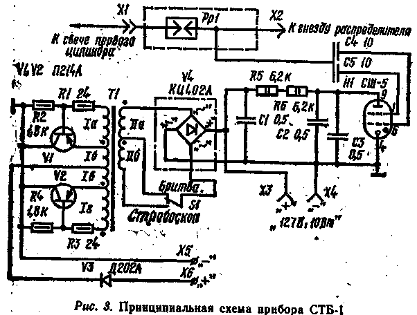
Fig.3
In the "Razor" strobe light operates as follows.
After connecting the terminals X5, X6 to the terminals of the battery starts working voltage Converter, which represents a symmetrical multivibrator. The Converter transistors alternately unlocked and locked by connecting one or the other half of the winding 1 of the transformer T1 to the battery. The result appears in the secondary windings an alternating voltage of rectangular shape with a frequency of about 800 Hz. Voltage winding IIA through the contacts of switch S1 is supplied to the rectifier unit V4, is rectified and fed to the nest XS,X4 electric razors.
When the switch S1 "Strobe" to the rectifier unit V4 receives the total AC voltage from the windings 11a and 11b, which is rectified and through resistors R5, R6 charges the storage capacitors C2, C3 to a voltage of about 450V.
At the time of sparking in the first cylinder of the high-voltage pulse from the nest ignition distributor via connector x2 discharger PP1 and capacitors C4, C5 comes on, igniting electrodes stroboscopic lamp H1. .The lamp is lit, and storage capacitors C2, C3 is discharged through the lamp. Thus the energy stored in the capacitors C2 and C3 is converted into light energy of the flash lamp. After discharge lamp capacitors H1 goes off, and the capacitors C2 and C3 is again charged through resistors R5, R6 to the voltage of 450 V. thus ends drafting to the next flash.
Capacitor C1 eliminates the emissions of the voltage on the collectors of transistors VI, V2 in the moments of their shift.
Diode VEARTH protects the transistors V1, V2 from failure when polarity of the strobe.
The discharger PP1 connected between the distributor and the spark plug provides .for under-jig the amplitude of the lamp voltage pulse regardless of the distance between the electrodes, the pressure in the combustion chamber, and other factors. Thanks to the discharger strobe works fine even with shorted the spark plug electrodes.
Schematic diagram of the device Auto-spark" is shown in Fig. 4. It consists largely of the same nodes as the strobe STB-1. Its difference - voltage Converter is made a little differently: the starting offset to the bases of transistors is supplied with a single divider voltage R2R3 connected to the midpoint of the base winding III. To facilitate starting of the Converter . the resistor R2 is shunted by the electrolytic capacitor C1.
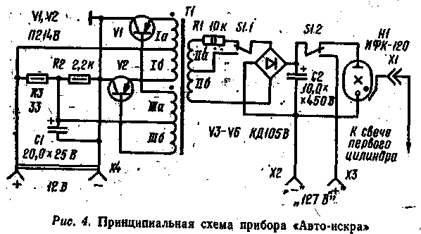
Fig.4
The transformer also has other winding data. The limiting resistor R1 is included to the rectifier bridge.
The storage capacitor C2 is electrolytic - with a capacity of 10.0 µf, stroboscopic lamp - IFC-120.
The use of this lamp has caused the change in the parameters of the storage capacitor - charging voltage is reduced to 250-300 In" and the capacity increased to 10 UF, however, the brightness of the flashes turned out to be much lower .than that of the strobe signal STB-1.
Differently executed commutation type of work. The time constant of charging the storage capacitor C2 is almost 10 times more than the STB-1, so the device Auto-spark" can be used only at low frequencies of rotation of the motor shaft (up to 800 rpm). At high frequencies the capacitor C2 does not have time to charge^ the pauses between two flashes, and the brightness of each flash is reduced.
The strobe STB-1 (see Fig. 1) made of plastic in the form of a gun with a trigger. The trigger 1 controls the switch S1 (see Fig.3). When you press the trigger switch is set to "Strobe". At the same time the body of the trigger closes the socket X3, X4 connection shavers, where at this time the voltage reaches 400 to 450 V.
Spring clips "crocodile" (X5, X6) are engraved polarity and enclosed in colorful rubber cases. The body of the adaptor-spark PP1 plastic, the distance between the electrodes is 3 mm, fork x2 and socket XI made of stainless steel.
Capacitors C1, C2, C3 - MBM for a voltage of 600 V. the Capacitors C4 and CS is made of a thin brass tube placed over the insulation of high-voltage wires PVA connecting the strobe with the discharger.
The transformer T1 is wound on the toroidal core OL HH. The windings 16 and 1B have 40 turns of wire sew-2 with a diameter of 0.51; winding 1A and 1G - 8 turns, and winding 11b-440 turns of wire sew-2 with a diameter of 0.19. Winding 11a-1160 turns of wire sew-2 with a diameter of 0.1 mm.
The device Auto-spark" is made in a rectangular case made of high impact polystyrene (see Fig. 2). Located on the body of the socket X1 for connecting the high voltage wire PVA connecting the device to the spark plug of the first cylinder of the engine, sockets x2, X3 for connecting the shaver and switch kind of work B1. The cord ends coaxial connector X4. For connection to a spark plug of the first cylinder is a special metal tendril 1 mounted on the other end of PVA. Switch S1 - TP1-2. All windings of the transformer T1 is wound wire sew-2 with a diameter of 0.2 mm. Winding 1 has 35+35 turns, III-50 + 50, coils, II-870 turns taped coil 460. Core OL 20x32x8.
Connecting devices should be made while the engine is stopped. When polarity of the terminals of the strobe STB-1 will not work.
The device Auto-spark" can be used on other vehicles, if you make a special adapter to coaxial plug X4 power, or completely remove the plug and replaced the wires soldered spring clips "crocodile". However, it should be borne in mind that in case of reverse polarity Auto-spark" will immediately fail. Of protection circuits in the device no.
When properly connected, power should be heard the distinctive squeak of pure tone (500 Hz) resulting from the operation of the Converter.
When working with the strobe STB-1 weak flash lamp can be observed without pressing the trigger, which is not a malfunction of the device. When you press the trigger the brightness of flashes increases several times.
Vibrating razor ("Era", "Neva", etc.) to connect to the device since it can incapacitate him.
Time of continuous operation to avoid failure should not exceed 10-15 minutes Should beware of touching the moving parts of the engine, in which a strobe light seem to be fixed.
Author: A. Sinelnikov; Publication: N. Bolshakov, rf.atnn.ru