


")

Motorists know how important proper installation of the ignition timing fuel in the cylinders of the engine carburetor. To do this, use strobe lights. In the article by P. Bialiatski "Led car strobe" ("Radio", 2000, No. 9) described a simple device with a lamp in the form of an Assembly of bright LEDs instead pulse photolamp.
The author of this article proposes to assemble the device based on the laser pointer.
We offer our readers a stroboscopic device allows not only to establish the optimal ignition timing (OZ) at idle engine, but also to find the faulty spark, check the ignition coil, monitor the work of centrifugal and vacuum regulators angle on 03 the engine speed to 3000 min-1 (high incidence of hazardous engine running without load). The appliance is not designed for use on service stations, but can provide an invaluable service to the motorist, stuck in transit due to faults in the ignition system.
Diagram of the strobe is depicted in Fig. 1. Pulses with high voltage chart the wire, after passing through the input unit consisting of a differentiating circuit C1, R2 and limiting resistor R1, trigger a single-shot, assembled on the elements DD1.1, DD1.2. The output pulses of the single vibrator duration of about 0.15 MS arrive at the base of the composite transistor VT1VT2, working as a current amplifier. In the collector circuit of the transistor laser pointer on BL1, serving as a load the amplifier. Because the output pulses of the single vibrator have a high level at while their actions are a composite transistor is opened and the laser pointer forms light flashes.
Pointer is designed for a supply voltage of 4.5 V, and it's powered stroboscope the on-Board network voltage of 13.8 V, the maximum duration of the output pulses the single vibrator should not exceed 0.15 MS - value is chosen experimentally and cost several "burned" lasers. At a pulse duration of more than 0.15 MS the average power dissipated by the laser power reaches the maximum allowable and sharply increases the risk of burning up the pointer, but at a lower mark on the crankshaft pulley becomes visually "subtle". It is also necessary to remember that the frequency of flares more than 100 Hz (corresponds to the rotational speed of a crankshaft of the engine 3000 min-1) dangerous for the pointer, operating at a higher voltage.
Structurally, the stroboscope consists of a sensor ignition pulses, coupled to chart wire of the first cylinder of the engine, and actually pointers, inside of which put all the other parts. The sensor is connected to the pointer shielded cable length 50 cm.
The basis of the sensor ignition pulses serves as a Laundry clothespin, on the side face hosting details C1, R1, R2 input node. One of the halves of clothespins in the place where the working proterties, is wound round tape of a width not more than 3 mm of tin or sheet of copper in the form of a bandage (Fig. 2). To him solder the capacitor C1. The output resistor R1 is brazed to the Central the wire and resistor R2 to the screen. Cable wire the brace is attached to the handle clothespins. On top of the details of the input node to be cover with silicone sealant to protect against knocks strap IG PCB (on figure not shown).
For setup details strobe pointer must first be dismantled. Unscrewing the nozzle, set it to the ring-puller with axial thickness of 1…2 mm, so that it rested on the edge of the cylindrical housing. Then screw with force the nozzle gradually wypracowywa "stuffing" from the casing. If necessary, the operation repeat with a ring of greater thickness.
Attempts to dismantle the pointer without ring puller usually lead to damage to the edges of the casing, made of soft aluminum alloy. Squeezing the "stuffing" out of the casing from the battery compartment, as shown practice also involves a risk of damage to the pointer.
From the disassembled pointer (Fig. 3) may be given to a push-button switch and side pliers carefully so as not to damage the resistor, shorten it to bar lines (traces shown in grey). If the resistor was still damaged, it does not matter enough conclusions to close the bridge, and the resistance of the resistor R5 in the diagram (see Fig. 1) to increase to 270 Ohms.
Details of the single vibrator and the output of the current amplifier is placed on a printed circuit Board from foiled on both sides of the fiberglass thickness of 0.5 mm. Drawing Board it is shown in Fig. 4 (a - side printing; b - side parts). Both transistors and the capacitor C2 is brazed by printing directly to the printed sites.
The holes under the chip must be such that it can be mounted close as possible to the Board - so it will be easier to insert into the casing of the pointer when an Assembly. Pin 7 of the chip and one of the terminals of the resistor R3 must be soldered with both sides of the Board. As the charges are quite "close", you really should try consider the sequence of installation of parts that do not have soldering already established. The chip mount last. Contact platform square shape on both sides of the Board must be connected segments copper wire and solder. Under the transistor VT2 should invest thin the insulation lining.
Before joining fee collected strobe with a prepared card pointer, it is advisable to check its operation with led instead of a laser. Led (for example, ALB) temporarily solder the anode to the positive output power, and cathode to the resistor R5.
In order to establish the strobe in the laboratory, it is advisable to collect by the circuit of Fig. 5 test the multivibrator. He produces short pulses of high repetition rate, adjustable variable resistor R2.
The pulses fed to the input of the strobe and choose the resistor R3 such that the duration of the output pulses does not exceed 0.15 MS.
After that, you need to make sure that the collected charge is freely into the casing pointer.
To the assembled Board soldered three flexible o - General, the input to the resistor R1 sensor) and the positive supply (+13.8 In), put it to a Board pointer the connecting foil pads out, in both Assembly hole cards insert along a section of copper wire of diameter 0.5 mm and probivaut. Don't forget a separate conductor connecting the positive output of the laser pointer on the Board (see Fig. 3) positive to the positive power wire on the Board of a stroboscope. Check again that will include whether the design into the casing pointer.
If everything is in order, inside the casing insert a rolled up insulator from slim hard plastic film and injected into the laser with the Board. End with conclusions pointer pour sealant. Flexible power pins with clips "crocodile" with the polarity markings or connector for connection to the outlet portable lamp.
In all cases it is advisable to break the plus wire to enter a diode that protects the strobe light from accidental activation of the strobe in reverse polarity (in the diagram Fig. 1 this diode not shown). You can use any diode for reverse voltage not less than 50 and In average rectified current of at least 100 mA. To mount the diode can close to an alligator clip.
In addition, given that the casing of the laser pointer is electrically connected to plus the cord, it must be carefully isolated and during use to prevent contact with parts of the car. Nevertheless to work with the strobe will be easier, if consistent with protection diode include miniature fuse on the current 0.16 A (not too shown).
For the operation of the strobe sensor-cling clothespins on set, high tension wire the first cylinder of the engine. Triggering pulses are received at the device via the capacitance between the ignition wire and brace for the working sensor. The tank should be the minimum necessary for a steady run.
If the capacity to choose excessively large, the amplitude of the trigger pulse when adverse circumstances can exceed permissible for the chip and cause its deterioration. So at the beginning of the sensor should be installed on the wire using a dry strip with a thickness of 1 mm made of polyethylene or PVC. If you run strobe is not happening - no flashing illumination of the laser on the smallest engine - gasket must be replaced more subtle.
To work with strobe easier when the light spot has an elongated shape - it facilitates the fixation of both labels in the field of view. Therefore, the pointer wear one of the included attachments, pulling a spot in line. When working in bright time of day, but in the shade, you can do without nozzles (the brightness of the spot will be more) aiming beam only on the moving label. Fixed the label on the case will be in these conditions and so well seen. To protect the laser and the attachment of dirt and dust in storage, be sure to use the appropriate case from plastic.
Perhaps someone seems easier to collect a single-shot strobe on miniature chip CLE. The drawing Board for this option is shown in Fig. 6. Here on the side parts (Fig. 6,b) only soldered the capacitor C2 and the transistor VT2, other details - side printing. In addition, with input the node is connected to pin 2 of the chip.
Before working with the strobe light wipe with a white paint mark on the housing and the pulley the crankshaft of the vehicle engine. If the mark is not painted, must to do this is very useful in the future. Well the engine warmed up, turn to idle 600…800 min-1. Connect the terminals of power strobe, his leads are not in contact with high voltage. Install the sensor on the high-voltage wire of the first candlestick and point the laser beam at a fixed label that is located on the housing. Then locate the laser beam is movable on the label the pulley flywheel - brightness spots in this place increases because of the reflection from white paint. If the label is not painted, the brightness of the reflected beam, on the contrary, will decrease, but it's harder to fix, especially in bright light.
Make sure that you have found the place - really a label, a little by changing the rotational speed of the motor shaft, wherein the label is shifted forward or back during the rotation of the pulley.
If setting the ignition timing on your car is broken, movable label can be very far from stationary. At idle mark on the pulley the flywheel should be opposite the middle fixed point, i.e. the angle ignition timing must be equal to 5 degrees. Rotation of the housing interrupter-distributor ignition control until convergence of mobile and fixed labels and lock it in position.
Momentarily increase the speed and see the divergence labels. With increasing the rotational speed of the crankshaft, the ignition must be earlier. On speed 3000 min-1, the ignition timing for automobiles should to be in the range of 15… 17 deg. [2].
Do not increase a rotational speed in excess of 3000 min-1 - it's dangerous for the engine, and for the laser pointer. In any case, do not point the laser beam in the eye!
In the strobe used laser pointer with power up to 1 mW. Lately appeared in the sale of laser pointers to five times brighter. They have the same the dimensions and their application in automotive strobe light is preferable.
Literature
- Bialiatski P. Led car strobe. Radio, 2000. No. 9, p. 43, 44.
- Ershov, B. V., M. A. Yurchenko cars VAZ. - Kiev, "high school", 1983.
Author: N. Zaets, POS Veidelevka Belgorod region; Radio No. 1 2004
Supplement
Automotive strobe light from the laser pointer" - under such heading in "Radio", 2004, № 1, p. 45, 46, was published the article of N. The Zayets. I liked the idea of using a laser pointer as a strobe light. For those who I would like to repeat this design, but does not know the device pointer, offer get to know her more.
The figure shows the "filling" pointer-stick. The light source is semiconductor radiating crystal 3, soldered to a massive base, official heat sink 2. A heat sink attached to the circuit Board 1 on which mounted power button, current limiting resistor and spring contact the battery power. Heatsink tight Board inserted in the slot in the sleeve-holder 4, at the other end of which is cut external and internal threads.
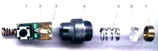
The light from the crystal is more diffused in the thin light it collects lens 6. Position the lenses relative to the crystal can be adjusted by a threaded bushing 7. Spring 5 presses the lens to the sleeve.
To use the pointer as a strobe illuminator better to defocus the light beam by screwing the sleeve until it stops (but do not push hard!). As a result the diameter of the light spot at a distance of 1 m increase to about 6 cm smaller distance spot diameter will be smaller. Anyway with a wider, what's the point, a spot to hold the label on the motor pulley is easier, and the danger to of view less accidental exposure to the beam.
Many articles focused on the fact that the pointer is powered from the source a voltage of 4.5 V, but the presence in its structure of current-limiting resistor indicates that the voltage can be anything, just to pick up the required current. Exactly included laser strobe. To calculate the resistor I need to measure the current of the laser pointer and the voltage drop on it. Samples of the laser, available to me, fell 2.6 V at a current of 35 mA. When choosing a current limiting resistor is not necessary to forget about the built-in resistor 68 Ohms.
In the process of conducting experiments on nutrition pointer high current one was spoiled. But, as it turned out, the crystal remained intact, and have thin thorel conclusion. The laser's operation was restored by the drop of conductive adhesive. Used tools - sewing needle and the lens 6.
Author: A. Chepurin, Chusovoy, Perm region.