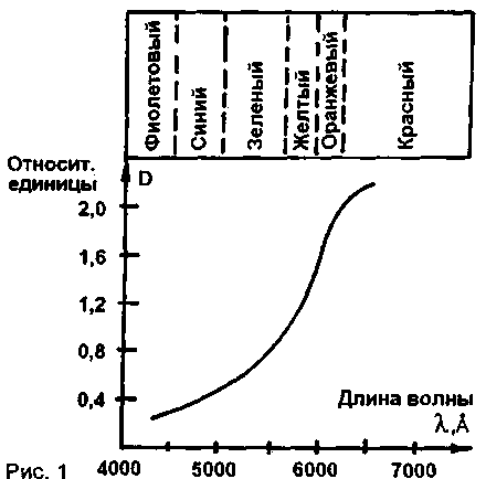
Consider the usefulness of automobile dimming device for the driver. On the chart (Fig.1) the intensity distribution of the radiant flux of an incandescent lamp [1] shows that the largest proportion of the red, orange and yellow rays, which are mostly and Shine the retina of the driver. In order to "cut off" the brightest part of the spectrum of the vehicle, many drivers put at the top of the windshield passive filters from bands of blue or green Plexiglas. However, passive filters is very inconvenient, since they are above the main field of vision of the driver.

Fig.1
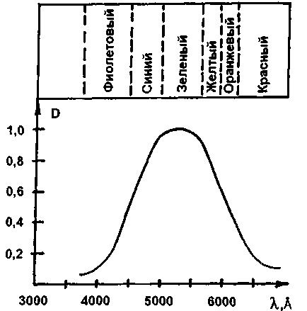
Electric dimming lights is mounted on the main level of the field of view of the driver on the left side of the windshield that does not disturb the driver while driving. The light from the light propagates parallel to the windshield and misses the driver's eyes, for this lamp has a light-shielding visor. When you turn on the light is absorbed a significant portion of the radiant flux of light of headlights, reducing the illumination of the retina. Furthermore, the use of the light blue or green filter gives you the ability to control the situation on the road, because at night the human eye is most sensitive to blue and green rays (Fig.2) of the visible spectrum [1].

Fig.2
The disadvantage produced by dimming lights is their early or later inclusion. Especially dangerous is the latest inclusion of a time when a sudden bright light illuminates the retina of the eye, and lamp switch is ineffective.
The proposed scheme automatically turn on and off the lamp has the following advantages over published in [2]:
- inclusion of the entire device occurs simultaneously with the car headlights from his "regular" switch;
- quick switch when lighting photocell beam headlights of oncoming traffic and smooth (units of seconds) cut off time readaptation of the driver's eyes.

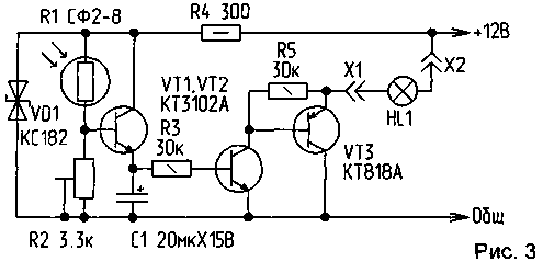
In Fig.3 is a schematic diagram of the automatic device on and off dimming of the lamp. It consists of a threshold amplifier luminous flux transistor VT1, composite transistor switch transistors of different conductivity VT2, VT3 and delay circuits turn off the lamp HL1 performed on the resistor R3 and the storage capacitor C1. The device is powered by a parametric stabilizer on the Zener diode VD1 and the resistor R4. The device turns on together with the vehicle. As soon as the rays of the headlights of oncoming traffic fall on the photo-resistor R1, the transistor VT1, which includes transistor switch VT2, VT3, and the lamp of the lamp HL1 enters the on-Board voltage +12 V lamp begins to Shine. At this time, simultaneously, the charge of the capacitor C1. When the illumination of the photoresistor is terminated, the transistor VT1 is closed, but the lamp HL1 continues to Shine up to full charge the storage capacitor C1 through the resistor R3 and bazo-emitter junction of transistor VT2. A trimming resistor R2 sets the threshold for inclusion lamp lamp HL1.
Structurally, the circuit Board is disposed in the lamp housing. For photoresistor drill a hole in the hull from the side facing the road. Although the sensitivity of the circuit is sufficient to increase its effectiveness in front of the photoresistor is advisable to set a converging lens. Optical system (photoresistor with lens) is positioned so that it is well illuminated by the headlights of oncoming vehicles and as little as possible with the headlights of your own car.
The lamp power in the lamp must not exceed 5 watts, photoresistor R1 type SF-8 can be replaced by FGC-1 with tenovym resistance 30...60 kω, the transistors VT1, VT2 must have a static current transfer ratio of at least 100. The transistor VT3 is used without a radiator and can be replaced by CT with any letter. Capacitor C1 type K50-16 can be replaced with any capacity 20...30 UF. The trimmer R2 - type GPA-6A. The Zener diode VD1 COP 182 can be replaced by DA.B.
Literature
1. Henochowicz S. A. quick reference in physics. - M.: Higher school, 1969.-C. 111, 114.
2. Bernolakovo E. the Electronics in everyday life. Radio. - 1984.-N2.-C. 56.
Author: P. Bialiatski, Novosibirsk region, Berdsk; Publication: N. Bolshakov, rf.atnn.ru


