


")

The circuit power supply form factor ATX, by using a vehicle battery.
This article describes the scheme of home-made power supply that can support the health of modern motherboards ATX and computer peripherals when used as an energy source car battery +12V.
The design formed the scheme is published on the website http://carmp3.nm.ru. However, this power supply would normally work only with the old M/B format AT, since it was developed only voltage ±12V, +5V and signal Power_Good. -5V is required for some motherboards based on nVidia chipsets (old ISA specification does not consider the effect of irrelevance), +3.3 V for normal operation of the processor P4. Also implemented a mechanism advanced power management (now to turn on and off B/N you can remotely, on a signal with M/B).
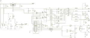
Fig. 1. A schematic diagram of B/a (click to enlarge)
The basis of B/a is PWM (TL494 or equivalent). Two MOSFET field-effect transistor commute constant voltage 12V from the battery to pulse transformer TR1. The output voltages are removed from the secondary windings, after rectification to half-cycle rectifiers D3-D12, and then reach a common choke DR1 and individual L-filters DR2-DR6.
Stabilizes the voltage of +5V, the other indirectly. Feedback stabilizer obtained from the programmable voltage reference TL431, the output part of the circuit untethered from input optocoupler PC817.
The inclusion of B/N on-Board network, and signal processing PS_ON remote control carries out control circuit of transistors Q1-Q2 and the relay RL1. For sure the relay you may need to select values of resistors R1-R2.
Standby voltage +5В_SB generates the integral stabilizer KREN (or imported analog 7805). This voltage is always while terminal connected to the battery, so the chip to be installed on the heat sink.
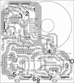
Fig. 2. A printed circuit Board (click to enlarge)
Structurally, B/N is executed on a single-sided PCB size 85?95mm, side view of the parts shown in Fig. 2.
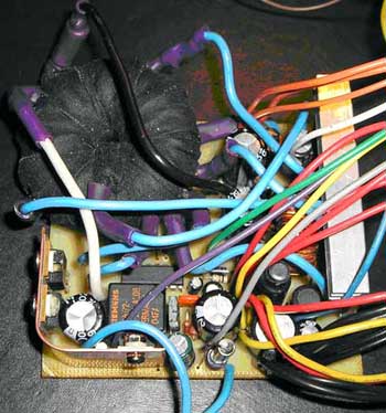
Fig. 3. Photograph of the finished design
Transformer dangle copper single-conductor wire in the varnish insulation diameter of 1 mm in 2 strands, i.e. the total cross section was about 1.5 mm2. Ferrite brand MNM-36 size 45?27?12. As the insulation of the windings used black cloth duct tape (of varnished cloth at hand, unfortunately, was not). The procedure for winding on ferrite is formed tightly wound primary winding double wire 2 braids for 6 turns each. The first end connects with the beginning of the second, it will connect to +12V battery (point #3 in Fig. 2). The free ends of this winding is connected to the transistors Q1 and Q2 (points #1 and #2 in Fig. 2). Next, wrap the insulation layer, and stacked secondary winding. The secondary winding is also symmetric, consists of 2 halves. Each half in turn consists of 2 segments 8 and 6 turns. The two halves are connected by risers 2 6-turn windings (earth or fine #4 in Fig. 2). From the joints of 8-and 6-turn windings are removed ±5V, made the bends (point #7 and #8 in Fig. 2). With the free ends removable ±12V (points #5 and #6 in Fig. 2). Winding for +3.3 V dangle over the top, after the insulation layer. It consists of 2?7 turns (two halves, 7 turns each), the middle portion are connected to ground (exact #4 in Fig. 2). Loose ends - points #9 and #10 in Fig. 2. All windings are, of course, travel in the same direction. Because solder is such a bundle of thick wires is very difficult, the outputs of the windings together with a flexible mounting wire made out of copper liners.
General choke DR1 is taken from computer B/N, DR2-DR6 - from the same place. Diodes D3-D8, D11 D12, D6 and D5 - in the case TO220 also wydany from a computer power supply. The rest of the diodes of the rectifier diodes of the Schottky current 5-7 A. Optocoupler also extracted from the same B/N, can be replaced by any similar.
Relay - any on 12V and the switched current 20-40 A. I took the relay from the car alarm. Diodes D1 and D2 also any, just to fit current.
Diodes, field-effect transistors and integrated stabilizer are mounted on the radiator through the insulating strip. The value of the tripping current of the protective fuse is determined experimentally, based on the capacity of the existing load. After debugging, it is desirable to fill the whole scheme in the compound or epoxy resin to prevent corrosion and mechanical damage B/P.
Author: Alexey Kazakov (Alex K); Publication: www.cxem.net