We are talking about different versions of electronic ignition devices (UEZ), designed as transistors and IC. No scarce items, as well as the simplicity of the schemes allow you to collect the electronic unit ignition even ignorant in electronics motorists. UEZ can work together with the ignition coils B-117 B-117 and B-115V used in cars "Lada", "Moskvich" and "Zaporozhets", and since it lacks a a special transformer to the storage capacitor device almost does not consume current when the ignition is on, has small weight and the dimensions.
Consider first the operation of the UEZ transistors (Fig. 1).
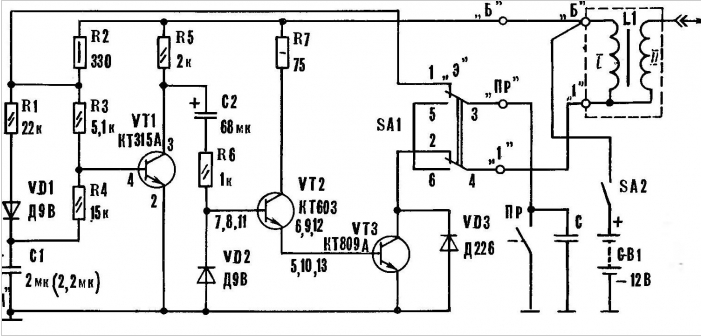
Fig. 1. A schematic diagram of a transistorized version UEZ
When turning the key in the ignition switch closes the contact pair SА2 and the 12 V battery battery CB1 is supplied to the electronic device and the ignition coil 1.1. When breaker PR is open, the battery current flows through the resistors R3 and base transistor VT1. It will open, and the transistors VТ2 and VТ3 will remain closed - current through the coil L1 flows through. In this case, consumption of the ignition system current will be about 10 mA, the magnitude of which is determined by the resistors R2, RЗ and 1R5.
If the PR contact is closed, the current flows around 40 mA. The battery voltage drops across the resistor R2 and the transistor VT1 is locked. The chain of R5, C2, R6 and through base VТ2, VТ3 current flows to charge the capacitor C2, opening these transistors. In the result of the current in the ignition coil increases to a value of 3.5 A.
As the charge of the capacitor C2, the voltage across it increases and the base current transistors VТ2, VТЗ gradually decreases.
During cranking of the engine breaker opens. From battery CB1 through resistors R2, R3 and VT1 base current begins to flow at about 2 mA. Transistor VT1 is opened and the capacitor C2 will discharge through the circuit: VT1, VD2, V6.
During and after the discharge of the capacitor C2 transistors VТ2 and remain VТЗ locked, the current through the ignition coil is not leaking.
Simultaneously with the discharge of C2 is the charge from the battery through resistors R2, R1 and diode VD1 capacitor C1. Elements R2, R1, R4, VD1 and VT1 base form a divider voltage, therefore, the capacitor C1 does not exceed 5 V.
Subsequent contact closure OL transistor OUT locked immediately, since Q4 through resistor and the base of transistor begins to discharge the capacitor C1. The time of his discharge is selected such that the locking VT1 (unlocking VТ3) ahead of the regular time of opening the contact PR (lock VТ3) for the period, sufficient to increase the coil current to the value that ensures upon opening the interrupter powerful spark to the spark plugs.
Locking of the transistor VT1 leads to the charge of the capacitor C2 through the chain of R5, C2, R6, base VТ2 and VТ3. However, due to the large time constant of the circuit C2 is charged slightly, and proceeding through the base VТ2 current is determined by the values resistors R5 and RB. When using VТ2 starts to leak current, the transistor VТ3 opens in the ignition coil starts to increase the current, which at the time of breaking contact PR reaches a value sufficient to form a powerful spark in the spark plugs.
The larger the capacitance of the capacitor C2, the easier the engine starts winding a handle.
At the time of opening the contact pair OL transistor VT1 is opened and the transistors OUT and VТ3 sharply locked, the current in the ignition coil is interrupted at its windings there is a voltage higher than a similar build in a conventional system the ignition. Moreover, the energy stored by the coil, flows directly to spark plugs, bypassing the capacitor C connected in parallel to the breaker, and the resistance of the primary winding. As a result, the heating of the ignition coil significantly reduced.
With increasing engine speed, the period of the closed state of the breaker approaching the rise time of current in the ignition coil. At the same time is reduced and the period of the opened state of the contact pairs, resulting in a reduction energy stored by the capacitor C1, and therefore to a decreased latency unlocking the transistor VТ3.
UEZ can be constructed with the use of an integrated circuit (Fig. 2).
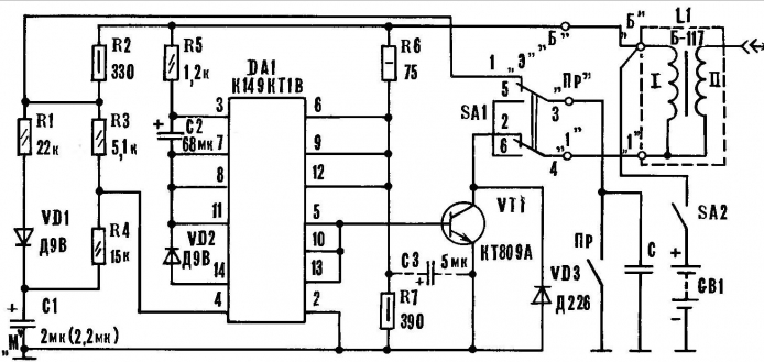
Fig. 2. Schematic diagram of the UEZ on the chip
The design of the device designed for operation with the ignition coil B-117,- figure 3.
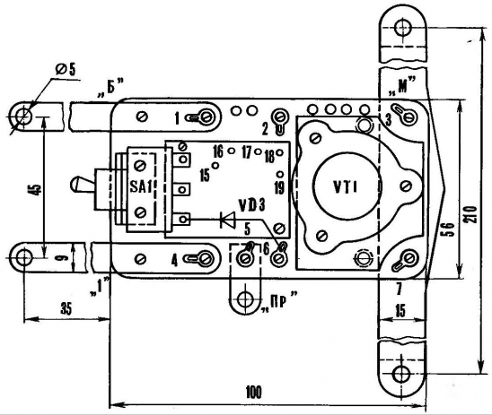
Fig. 3. Block design UEZ
All components and parts are fastened with screws on the panel size mm h sheet PCB thickness 2-3 mm In the center of the printed circuit Board (Fig. 4), made of one-way foiled fiberglass thickness 2-3 mm. Connect as follows: pin 15 is connected to the base transistor VT1; 16 - petal 1; 17 connects to pin "1" of the switch SА1; 18 - to terminal B; 19-petal 2. Part of the elements, not shown in the figure 3, placed and connected as follows: the resistor R2 is connected between the output "1" switch SА1 and petal 1, resistor R6 between lobes 1 and 2, the resistor R7 is between 2 and 3; petals 6 and 7, the jumper is plugged; the emitter of the transistor VT1 is connected to the petal 6, and its collector to the conclusion "2" SА1, its output is "4" is connected to the petal 4, and conclusion "3" - to the 5 petal. Switch SА1 fixed to the bracket 9 and is raised above the motherboard at 10 mm. Capacitor C3 is inserted between the petals 2 and 6.
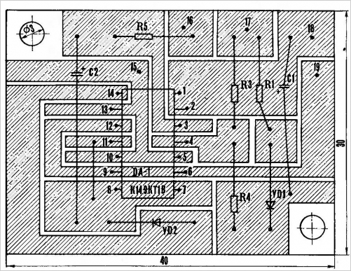
Fig. 4. Circuit Board UEZ on the IC
Conclusions UEZ for inclusion in the ignition system is made of sheet aluminum 1 mm thick. at the same time they are used for fixing the unit to the coil the ignition. Conclusions "B" and "1" are fixed on the respective terminals of the coil ignition, and "M" forms a clamp to it and tightened the screw.
The casing UEZ - plastic or metal, height 30 mm, With one hand he fastened with the nut switch SА1 and two long screws (pillars), which are used for fastening the clamp "M", petals 3 and 7. The cover should cover the circuit Board and a few to hang with her, in order to reliably protect the device from water or oil. For radiator cooling transistor VT1 in the circuit Board and in the upper part of the side casing adjacent to the radiator from the output of "PR", drilled a few the holes.
The electronic ignition device is not critical to the possible location details, and its design can be any. However, when mounting the UEZ note that the radiator of the transistor VT1, conclusions "B", "PR" and "1" are live, so they need to wear vinyl chloride tube.
Connection with the switch SA1 and the emitter of the transistor with the petals should VT7 run a wire cross section of at least 0.5 mm2. Wiring diagrams UEZ to the system the ignition coils B-117 and B-115V shown in figure 5. The wire from B-115V, going to the starter relay, unplug it from the ignition coil.
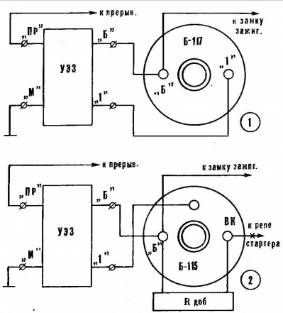
Fig. 5. Circuits on the UEZ ignition coils: 1 - B-117, 2 - B-115V
Details UEZ. All type resistors MLT. Diode VD3 must have a valid return the voltage of at least 350 V and direct current of at least 100 mA. Capacitors C2 and NW - K53-1 with an operating voltage of 15 V. it is Possible to use a capacitor K53-4 and others, capable of operating in the temperature range -40°C... +70°C. S1 - K53-1A, K53-4, better metalloboranes MBGP, MBGC.
As transistor VT2 can be used CT, KTV, and instead KTVA - CTA (IN). Instead of the resistor R2 is better to install the lamp SM-37, which will allow supervise the work of the UEZ, breaker contacts and will serve as an indicator for setting the initial ignition timing. In addition to CM-37 can be used switch light bulbs for a voltage of 24 V with a current up to 100 mA.
Before installing UEZ on the car you should test it with an electrical current. For this to terminals "B" and "M" connected, respecting the polarity of the power source voltage 6-12 In and to the terminals "B" and "1" to control the light bulb is a 12 volt power more than 5 watts. If there are no errors in the installation it should not burn. Then, periodically shorting between terminals "A" and "M", make sure that any the position of the switch SА1 warning lamp lights up to the beat-circuit these the terminals.
Select SА1 in position "e". Holding in closed condition terminals "A" and "M", make sure that the warning light, flushing begins relatively slowly disappear. After that UEZ can be installed on the car. The engine will run normally. If with increasing speed he works abnormally, it indicates a larger gap between the contact the breaker plates and should be slightly reduced.
To guarantee long lasting reliable performance desirable full scan UEZ. Spend it in the following sequence:
1. Includes DC ammeter 5 And the circuit wires leading from the castle plug to terminal "B" of the ignition coil (it must be connected and the terminal "B" UEZ). Switch BE set to "electronic ignition".
2. Turn on the ignition and make sure that the ammeter will show the inrush current of about 3 A with its subsequent reduction to 0.05-0.1 A (in case of leakage of the capacitor C2 this current may be greater than 0.1 A, but should not exceed 1.1 (A). If the current is not subsides, then immediately switch off the ignition - UEZ faulty. When inrush current no, turn a little crank shaft (contact breaker could be open-circuited). In low inrush current, it is necessary to reduce the resistance resistor R6.
3. Start the motor and measure the current consumed by the ignition system. If the current more than 1.1 And, it reduces a slight increase in the gap of the contact system the breaker. Warm up the engine.
4. Increasing the engine speed, watching the readings of the ammeter. The first current may increase, but not to exceed 1.1 A, and then to decrease to 0.6 to 0.7 A. If current less than 0.6 A, it is necessary to increase the resistance of the resistor 1?1 (from 22 to 27 com), despite the fact that the engine can stably work at all speeds. In operation UEZ no adjustment is not required.
For use UEZ motorcycle is recommended:
1. To reduce the magnitude of resistance of the resistors in two times, and resistor R5 to 1.5 com.
2. The capacitance of the capacitors to increase twice.
3. To measure the current flowing through the primary winding of the coil (transformer) the ignition at high engine speeds with conventional ignition.
4. To install on the bike UEZ and tested and the setting similar to performed on the car. In this case you may need to change the capacity capacitor C1.
Flowing from the ignition to the coil current should not exceed 1.1 A. When a voltage of 6), you can use the chip CCT.
Transistor variant UEZ will greatly simplied if we exclude from the scheme switch A and elements that provide the unlocking delay transistors VT2 and VT3. Schematic and PCB simplified electronic version plug - in figures 6 and 7.
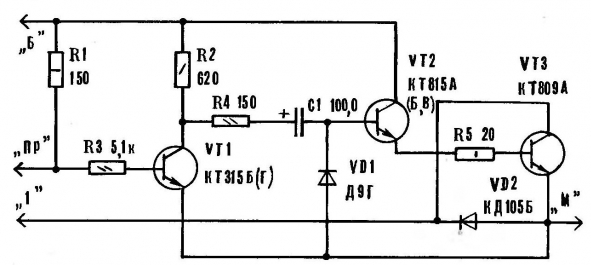
Fig. 6. A schematic diagram of a simplified version of the UEZ transistors
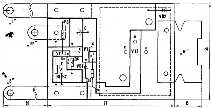
Fig. 7. The circuit Board is simplified UEZ
The disadvantages of this UEZ are the need for dismantling in the transition to conventional ignition; more loaded mode of operation of transistors, and the fact that the average current flowing through the ignition coil when the engine is running, almost the same as with conventional ignition. It's not eliminates heating of the ignition coil. However, a minimum of parts, simplicity structure and independence of the device characteristics on the magnitude of the gap between contact breaker plates still provide a number of benefits last option UEZ before the previous one.
Author: B. Kruglov


