The problem of environmental pollution arising together with civilization and growing as it evolves, now require greater attention. This is because humanity continues to use as energy is the most available and cheapest sources, i.e. the hydrocarbon fuel.
Recently it has become clear that the greatest contribution to air pollution make cars. This is especially true of large cities. In addition to relatively harmless carbon dioxide (greenhouse effect is not yet believe), internal combustion engines emit a number of chemical compounds in the exhaust gases are uncontrollable currently used by analyzers.
Because the combustion chamber of the engine is high-temperature chemical reactor, seasoned with reagents such as nitrogen, carbon, hydrogen, lead, oxygen, sulfur and others.
Abroad is widespread catalytic converters using the property of platinum group metals (platinum, rhodium, palladium, etc.) to contribute to the additional oxidation (combustion) in the exhaust pipe, which managed to burn in the combustion chamber. However, they are short-lived, and are quite expensive (about 10% of the value of the car). But the question remains, what to do with our not-so-young fleet, which will still be operated it is unclear how much. This situation suggests the following output. Need to develop such an ignition system which is able to burn in the combustion chamber, in addition to increasing the efficiency of the engine.
The task of a more complete combustion of the air-fuel mixture in internal combustion engines to some extent managed to solve with the help of the ignition system, which is based on a new method of ignition of fuel [1, 2].
Oddly enough, the modern system of ignition of the fuel-air mixture used in common brands of cars based on the same method of ignition, and at the beginning of the era of motoring. This spark discharge between the electrodes of the spark plug. Description of the processes occurring at the moment of ignition of the fuel-air mixture and the combustion process are followed in the literature, as a rule, references to the lack of a unified theoretical model of this process and various explaining his different authors. It is known that the efficiency of the internal combustion engine depends on the temperature of the gases in the chamber combustion, which depends, in turn, the speed of combustion of the fuel-air mixture. Accordingly, with the increase of the speed increases engine efficiency and, as a consequence, reduced specific fuel consumption.
When developing a new ignition system it has been suggested that to increase the speed of combustion of the fuel-air mixture in the combustion chamber can weaken the effect of "lacing" the plasma formed between the electrodes due to the leakage in the spark gap DC. The current in this case is supported by the energy accumulated in the ignition coil. In the new system uses the principle of energy storage in the capacitor, providing a spark gap of a spark plug of the bipolar pulse current.
During the first period of oscillation of the voltage on the electrodes of the spark occurs the preparation of the mixture and its ignition, and during the subsequent burning. In Fig.1 shows a graph of the voltage across the spark plug electrodes. In the last two periods of the voltage pulses have a shape close to rectangular.
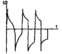
Fig.1
Diagram of the electronic ignition is presented in Fig.2. It works as follows. Capacitors C5 C7...charged from the secondary winding of the Converter transistor VT1 to a voltage significantly greater than the EMF of the battery. Upon opening of the contact breaker connected between the points PR and M, through the control electrode of the thyristor VD8 passes the current pulse generated by an RC-circuit R1, R2, R5, C1. The thyristor opens, and begins oscillating the discharge of the capacitor through the primary winding of the ignition coil connected to the point of short circuit. During the first half cycle current flows through the thyristor, and the second is through the diodes VD9, VD10.
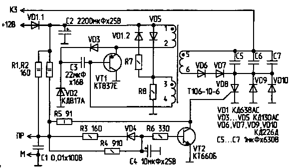
Fig.2
The process is repeated until such time as the capacitor C4 will not be charged until the voltage at which key opens the transistor VT2, which prevents another unlocking the thyristor. If the contact breaker residual voltage of the capacitor C4 is applied to the control transfer thyristor and securely locks it. Capacitor C4 is thus discharged through the resistor R3 and the diode VD4, however, the key VT2 some time after closing the contact remains open, which prevents accidental unlocking of the thyristor due to the bounce breaker contacts.
In the case of the use of the switch in the ignition system with Hall sensor, the latter directly controls the operation of the key. The processes taking place in the scheme similar to that described above.
The proposed scheme allows you to plug coupled to the spark plug electrode voltage, the polarity of which is reversed within one cycle of engine operation. The selection of elements of the control circuit provides the optimal duration of the discharge in the spark plug.
The use of the described method ignition makes it possible to increase the fuel efficiency of the engine, its power and throttle response, decrease the content of carbon monoxide in the exhaust gases and to increase the life of spark plugs.
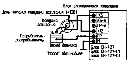
Fig.3
Connection diagram of the developed block (IT-427) to the ignition system of the vehicle shown in Fig.3 and 4. When connecting or disconnecting the unit, the ignition must be turned off and the terminal "Mass" ( - ) is disconnected from the battery. The electronic ignition unit made according to this scheme, tested on trucks and were compared with different staffing ignition systems.
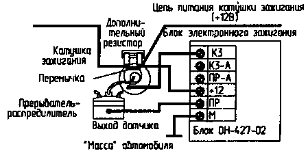
Fig.4
Were selected GAZ-52, classic contact system and GAZ-53 transistor with improved system and induction ignition sensor. The tests were carried out according to the method developed by NPMP "VITAR head". The test results of the developed unit is shown in Fig.5.
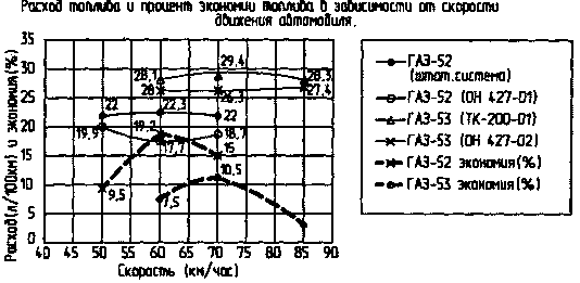
Fig.5
Analysis of the results demonstrates the effectiveness of the developed device and suggests that the nature of what is happening upon ignition of the fuel-air mixture processes to some extent described.
Literature
Author: V. Shcherbatyuk, Minsk; Publication: N. Bolshakov, rf.atnn.ru


