In internal combustion engines of most modern cars, the current ignition timing (03) operates mainly mechanical centrifugal Governor, which is inherent disadvantages such as instability characteristics and the complexity of its changes, rigidity, instability angle O3 caused by friction and backlash in the mechanism. We offer our readers an electronic device is almost free from these disadvantages. Thanks to "design flexibility" it can replace any centrifugal Governor. By the way, the relevance of this topic now suddenly increased. The fact is that in recent years Russia imported many cars equipped with electronic control units, ignition, from time to time fail. Replacing them in our conditions is not always technically possible, not to mention the fact that it is extremely costly. The output from these types of difficulties in some cases is to install a homemade blocks, such as described in this article.
Technical characteristics described below digital automatic angle Adjuster 03 are highly stable and do not depend on the ambient temperature. Possible fluctuations of the angle at a fixed rotational speed of a crankshaft of the engine are within ±0.25 degrees. Angle correction is performed every half crankshaft of the engine that provides almost businessconnect device. Digital controller is designed to work in conjunction with digital octane-corrector, described previously ("Radio", 1987, No. 10, pp. 34 - 37), but can work independently.
The principle of operation of the digital controller is based on the filling of the down counter pulses, the repetition rate of which depends on the rotational speed of the crankshaft of the engine, and the subtraction of pulses of fixed frequency. The entry in the counter begins at the moment of sparking, and subtract from it - at the time of opening operation of the breaker contacts. At the transition of the counter to 0 output pulse is generated that triggers the ignition system, then the process repeats. Time subtraction and determines the delay time of the output pulse relative to the time of opening operation of the breaker contacts, i.e. the angle of delay introduced by the regulator.
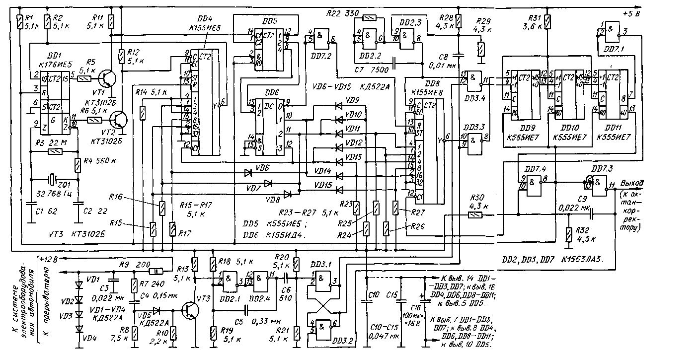
Schematic diagram of the digital controller shown in Fig. 1. The device consists of a node VT3, DD2.1, DD2.4, eliminates the influence of bounce breaker contacts, quartz timer DD1, VT1, VT2, DD4-DD6, encoders diode VD6-VD15 that determine the response regulator, generator of rectangular pulses DD2.2, DD2.3, the counter DD8 variable coefficient accounts, RS-flip-flop DD3.1, DD3.2, the reversible counter DD9-DD11 and controls. When shown on Fig. 1 the circuit diagram of the diode VD6-VD15 regulator according to the characteristics of similar mechanical centrifugal regulator R-147A installed on the vehicles M-im-2141.

(click to enlarge)
After switching on the ignition RS-trigger DD3.1, DD3.2 can be installed in any condition. Assume that the output element DD3.2 is a high level. Then pulses with a frequency of about 50 kHz from the output of the generator DD2.2, DD2.3 after dividing counter DD8 will arrive at the input +1 down counter DD9-DD11.
When the counter output 8 DD11 high level of signal element DD7.1 will prevent the passage of pulses to the output Y of the counter DD8 and filling down counter will stop. The number of pulses counted down counter will determine the maximum delay time of the output signal relative to the moment of opening of the breaker contacts.
After tripping of the breaker contacts a single-shot DD2.1, DD2.4 generates a low level pulse duration of about 500 microseconds, required to eliminate the effect bounce breaker contacts when they are open. Differentiated chain
C6, R20, R21, this pulse will switch the trigger DD3.1, DD3.2. The high level appearing on the output element DD3.1, will permit the passage of pulses of the generator DD2.2, DD2.3 to the input of -1 down counter, and the low level at the output of the element DD3.2 will prevent their passage to the input of +1.
The differentiating circuit C8R28R29 used for synchronizing the generator to the breaker contacts. When switching down counter DD9 - DD11 from state 0 to state 15 at the output of counter 0 DD11 formed a low level pulse.
The edge of this pulse triggers a single-shot, assembled on the elements DD7.4, DD7.3. The high level pulse from the output of the element DD7.4 will reset the up-down counter and the counters DD1, DD4, DD5, and the low level pulse (duration of about 20 MS) from the output of the element DD7.3 returns the trigger DD3.2, DD3.1 to its original state.
As the meter DD5 is in the zero state, the output 0 of the decoder DD6 will be a low signal, which after inverting element DD7.2 reset counter DD8 and keep him in this state. Therefore, while the output 0 of the decoder DD6 signal is low, fill down counter DD9-DD11 will not happen, despite the high level of the lower circuit on the input of the DD3.3, and a reversible counter will be 0.
The time during which the decoder DD6 is in each of States 0,1,2,3, is determined by the ratio of the invoice counter DD4, which, in turn, is determined by your state of mind at the moment is the decoder DD6, and a connection circuit diode VD6-VD8. The factor accounts for the counter DD8 also determined by the state decoder DD6 and the scheme of connection of the diodes VD9-VD15.
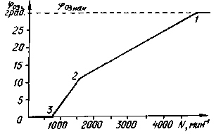
Consider the formation of the characteristics of the regulator shown in Fig. 2. In the above-mentioned article describes the principle of formation characteristics octane-corrector. In its composition also includes a reversible counter, but the frequency of filling and subtractive pulses does not change during one period of sparking. In this case, the angle of delay introduced by the device, is constant and does not depend on the frequency of rotation of the motor shaft. Feature octane-corrector - horizontal line.

Fig.2
Electronic automatic angle Adjuster 03 the pulse repetition rate, fill down counter, discretely varies within one period of sparking, and a graph of angle of 03 on the frequency of rotation of the motor shaft takes the form of a curve consisting of straight line segments. The position of breakpoints 1, 2, 3 depends on the time intervals during which the decoder DD6 is in each of States 0, 1,2, 3. The intervals determined by the ratio of the invoice counter DD4, which, in turn, depends on the scheme and the inclusion of diode VD6-VD8.
The pulse repetition rate, fill down counter while decoder DD6, in each of States depends on the ratio of the invoice counter DD8, which is determined by the switching circuit diodes VD9-VD15.
In accordance with the scheme regulator (see Fig. 1) at frequency of rotation of the motor shaft over 5000 min-1 or period of sparking less than 6 MS decoder DD6 will be in the state 0. Therefore, the input R of the counter DD8 will be a high level pulse at its output, the state of the reversible counter DD9-DD11 is not changed, the controller delays the output pulse relative to the input.
When reducing the rotational speed of the motor shaft (see point 1 in Fig. 2) the decoder DD6 switches to state 1, the input R of the counter DD8 appears low, we will fill the down counter, therefore, there will be a delay of the output pulse relative to the time of opening operation of the breaker contacts.
Changing the switching circuit diode VD6-and VD9 VD8-VD15 can widely change the characteristic of the electronic controller. The calculation of the coefficients of the account counters DD4 and DD8, and hence the schema definition of the decoders is quite complex (the size of a journal article does not allow you to bring it in full). For their calculation are written program (PL. 1) in the programming language "Q-Basic, which is part of the O. C. DPS 6.22 and Windows'95. Making minor changes in the program, it can be used on computers "Radio 86RK" and "Spectrum".
To run the program, enter the parameters characteristics of the centrifugal regulator of the model are taken from the technical description of the regulator. This is the angle of 03 and frequency of rotation of the motor shaft (not to be confused with the rotation speed of the Cam breaker) at the points 1, 2, 3 characteristics (Fig. 2). The result of the program is displayed in a form similar to those shown in table.2.

Tab.2
For example, when the decoder DD6 is in state 2, the required ratio of the invoice counter DD8 was equal 18/64. The maximum ratio of the counter K155IE8 equal to 63/64. To obtain the desired ratio of the invoice, you need to output 2 of the decoder DD6 to apply a voltage of low level to the inputs of the counter, the sum of the weighting values is equal 63-18=45, i.e. the inputs 1, 4, 8 and 32. On the other inputs must be single level.
This is ensured by the inclusion of diodes VD10, VD11 and VD15. The input of the counter 32 DD8 low fed constantly. In table. 2 are the coefficients of the account counters DD4 and DD8 and codes on their inputs in various States of the decoder DD6 to obtain the characteristics of a centrifugal regulator R-147A of the car "Moskvich-2140".
Author: A. Biryukov, Moscow; Publication: N. Bolshakov, rf.atnn.ru


