The regulator is mounted on the PCB of bilateral foiled fiberglass 1.5 mm thick. The drawing Board is shown in Fig. 3. Resistor R9 - MLT-2, others - MLT-0,125. The capacitor C16 - K52-1, others - km-6B or km-5.
Instead of diodes KDA (VD1-VD4) you can use any silicon, suitable for direct current of at least 100 mA (for example, CDA, KDA), the rest can be replaced by CDA, KDA, KDA. Transistors CTB any interchangeable from the KT315 with the current transfer ratio of at least 30. The values of capacitors and resistors can vary by ±20 %.
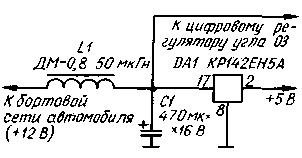
The power supply controller and digital octane-corrector must ensure that the voltage of 5 V±5% at load current of 0.7 A and the input voltage 8...14 V. Diagram of one embodiment of the unit shown in Fig. 4. Stabilizer DA1 mounted on the heat sink with a total area of about 200 cm2.

Fig.4
The operability of the machine check as octane-corrector: to input connect the contacts of the relay, the winding of which is connected to the generator AF through the diode DA. To the output of the element DD3.1 connect the oscilloscope and observe the high level pulses whose frequency is equal to the frequency of the input pulses, and the duration should increase with decreasing frequency. The period of the pulse corresponds to the angle 180 deg., and their duration - corner delay.
More precisely, the delay angle can be measured with a digital frequency meter. It is connected instead of the oscilloscope and measure the period and the pulse duration at the output of the element DD3.1. The delay angle (in deg.) equal 180t/T where T is the period and t is the duration (in MS) single pulse at the output of element DD3.1.
By changing the frequency of the generator, build a graph of angle of 03 on the frequency. He must coincide with the schedule shown in Fig. 2. Moreover, the Foz=30-F3, where (Foz - current angle OZ, F3 - delay angle (start angle OZ is equal to 30 deg.).
The controller output is connected conclusions 1 item DD2.1 and 4, element 5 DD3.2 octane-corrector, and the elements R6, VT1, C5, R13, R14, SA2 from the corrector removed.
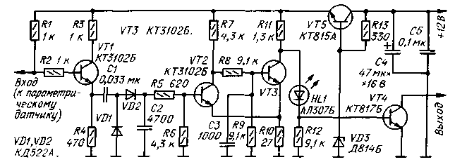
If the regulator is supposed to be used without digital octane-corrector, the output of the regulator should set the matching node is the same as the output octane-corrector - DD3.3, DD1.2, VT3, VT4, C7, R20-R23. The output signal of the regulator should be submitted on the pin. 10 item DD3.3 site. Although digital automatic controller is designed to work with the contact breaker is much more effective than its use in conjunction with a proximity sensor-breaker, for example, from the ignition unit BASS-1. The generator circuit that is required for matching the output of such a sensor and input circuits of the regulator shown in Fig. 5.

Fig.5
The former use resistors MLT-0,125, capacitors km-5, km-6 (C1-C4), K52-1 (C5). Transistors CTB can be replaced with any of a series of KT315 static current transfer ratio over 30 and the transistors CTB and CTO - nakhil CTB. HL1 led, suitable for direct current of at least 10 mA, serves as an indicator of setting the initial ignition timing.
The driver is installed in the engine compartment of the vehicle close to the interrupter-distributor.
The input circuit of the electronic unit BASS-1 should be amended to exclude the elements of R3-R8, V3-V5, NW, C4 (here the positional part numbers correspond to the diagram in the manual for your unit). The place should collect input node, similar to the one used in the digital controller (elements VD1-VD5, NW, C4, R7-R10, R13, VT3 in Fig. 1). Right circuit output resistor R13 should be connected to the positive power supply conductor block BASS-1, and the output node of the collector of transistor VT3 - to the base of transistor VT6.
After such modifications, the electronic unit BASS-1 can work with the output signals of the digital octane-corrector, shaper proximity sensor and conventional contact breaker.
Digital automatic controller installed in the vehicle, in a place readily accessible to the driver and is connected to the breaker and an electronic ignition system with shielded cable.
Before installing the regulator should either be dismantled centrifugal Governor, fixing the Cam on the axis, or to firmly secure it to the breadcrumbs. Then set the start angle 45 03 deg. relative to TDC (30 deg. - the working range of the digital controller; 10 deg. - the angle recommended by the manual for the car "Moskvich-2140"; 5 deg. - to ensure the operation of a digital octane-corrector). Next, specify the start angle at 03 traffic (according to normal procedures).
Power distribution plate of the rotor of the distributor preferably extend approximately 35 mm in the direction opposite to the direction of rotation of the shaft.
Author: Biryukov, Moscow; Publication: N. Bolshakov, rf.atnn.ru


