


")

This article focuses on further improving popular among motorists construction octane-corrector. The proposed additional device is substantially increases the efficiency of its application.
E-octane-corrector V. Sydorchuk [1], modified E. Adagamov [2], of course, simple, reliable in operation and has excellent compatibility with various ignition systems. Unfortunately, he, like other similar devices, the delay time of ignition pulses depends on the position of the handle install the ignition timing (advance angle). It means the installed angle optimal, strictly speaking, only for one value of the rotational speed crankshaft (or vehicle speed for a particular gear).
It is known that automotive engine equipped with centrifugal and vacuum machines, corrective advance angle depending on the rotational speed of crankshaft shaft and engine load, and mechanical installation octane-corrector. The actual advance angle at each moment determined the total effect of all these devices, and the use of e-octane-corrector obtained to the result is added another significant ingredient.
The ISP provided e-octane-corrector [2],  oz.OK=6Nt, where N is the rotational speed of a crankshaft of the engine, min-1 ; t is the time delay ignition, electronic insertion octane-corrector, p. Assume that the initial installation of mechanical octane-corrector corresponds to +15 degrees. and at N = 1500 min -1 the optimal delay of the ignition timing, set e octane-corrector equal to 1 MS, which corresponds to 9 deg. angle the crankshaft.
At N = 750 min -1 time delay will correspond to 4.5 degrees. and at 3000 min -1 - 18 deg. the angle of rotation of the crankshaft. At 750 min -1 result The advance angle is equal to +10.5 deg., at 1500 min -1 to +6 deg., and at 3000 min -1 - minus 3 grad. Moreover, at the time of activation of a node off the ignition delay (N = 3000 min -1 ) advance angle will change dramatically once at 18 deg.
This example is illustrated in Fig. 1 schedule based CPP ( ) from the rotational speed of the crankshaft of the engine. The dashed line 1 shows required dependency, and the solid broken 2 is actually received. Obviously, to optimize the operation of the engine by the ignition timing this octane-corrector able only during prolonged driving with the same speed.
However, it is also possible by simple modifications to eliminate this the fault and turn octanolwater in the device, creating a the desired advance angle in a wide range of frequency of rotation of the crankshaft. In Fig. 2 a schematic diagram of the node, which must be supplemented octane-corrector [2].
The node operates as follows. The low level pulses taken from the output inverter DD1.1, through the differentiating circuit C1R1VD1 is input to the timer DA1 connected in the circuit of a single vibrator. Output rectangular pulses the single vibrator have constant duration and amplitude, and the frequency proportional to the rotational speed of a crankshaft of the engine.
The voltage divider R3, these impulses are sent to an integrator circuit R4C4, transforming them into a DC voltage that is directly proportional to the frequency rotation of the crankshaft. This voltage charges the timing capacitor C2 octocorallia.
Thus, by increasing the frequency of rotation of the crankshaft in proportion reduces the time of charging of the timing capacitor to a voltage switching logic element DD1.4 and, accordingly, decreases the delay time, made e-octane-corrector. Required dependency changes the charging voltage of the frequency is provided by setting the initial voltage in the capacitor C4, remove from engine resistor R3 and adjustment the duration of the output pulses of the single vibrator resistor R2.
In addition, the octane-corrector [2] the resistance of the resistor R4 must to increase from 6.8 to 22 ohms, and the capacitance of the capacitor C2 to decrease from 0.05 to 0.033 ICF. The left circuit output resistor R6 (X1) disconnect wire from positive and connected to the common point of capacitor C4 and resistor R4 of the added node. The power supply for the octane-corrector served with parametric stabilizer R5VD2 extension node.
Octane-corrector with these modifications allows adjustment of the delay timing, is equivalent to changing the advance angle in the range 0…-10 deg. regarding the value set by the mechanical octocorallia. The characteristics of the device, with the same initial conditions as in the example above is presented in Fig. 1 curve 3.
When the maximum delay time of the timing error of maintaining the CPP in the interval of crankshaft rotation speed 1200…3000 min -1 virtually no, at 900 min-1 less than 0.5 deg., while in the idle - not more than 1.5…2 deg. The delay does not depend on change of Board voltage of a vehicle within 9…15 V.
Modified octane-corrector retains the ability to provide the spark by reducing the supply voltage of 6 V. If you want to extend the range regulation of the CPP, it is recommended to increase the resistance of the variable resistor R6.
The proposed device is distinguished from similar to that described in [3; 4], circuit simplicity, reliability and the possibility of interfacing with virtually any the ignition system.
In the extension unit used fixed resistors MLT, trimming resistors R2, R3 SP5-2, capacitors C1-C3 - km-5, km-6, C4 - K52-1B. The Zener diode VD2 you need to pick up the voltage stabilization 7,5 7,7…V.
The parts of the unit are placed on the circuit Board of foiled fiberglass thickness of 1…1.5 mm. Drawing Board shown in Fig. 3.
Fee node attached to the Board octane-corrector. All the device better just be mounted in a separate durable casing, strengthened near the unit the ignition. It is necessary to protect octane-corrector from moisture and dust. It can be in the form of easily removable unit mounted in salon the car, for example, on the side wall at the bottom left of the driver's seat. In this case, when removed octane-corrector, an electric ignition circuit will be open that, at least, make it difficult to start the engine outsiders face. Thus, the octane-corrector additionally function anti-theft device. With the same purpose, it is expedient to apply adjusting variable resistor CP3-30 (R6) with switch-over the electric circuit of the resistor.
To establish the device will require a supply voltage of 12…15 V, any low-frequency oscilloscope, voltmeter and a pulse generator, which can to do so, as specified in [1]. First temporarily disable input circuit timer DA1 and the slider of the resistor R3 is set to the lower (on) position.
The input octane-corrector serves a pulse frequency of 40 Hz and by connecting the oscilloscope output, the resistor R3 gradually increase the voltage on the capacitor C4 before the appearance of the output pulses. Then, restore the input circuit of timer connect the oscilloscope to pin 3 and the resistor R2 sets the duration the output pulses of the single vibrator is 7.5…8 MS.
Again connect the oscilloscope, translated in the external synchronization mode with waiting for scan-triggered input pulses (best to use the simplest dual-channel switch), to the output of octocorallia and resistor R6 set the delay time of the output pulse of 1 MS. Increase the frequency generator 80 and the resistor R2 sets the delay time 0.5 MS.
Then verifying the length of the delay pulses at 40 Hz, adjust if necessary, repeat until, while the duration at a frequency of 80 Hz will not be exactly two times less than at 40 Hz. This should keep in mind that to ensure stable operation of single-shot frequency to triggering node off delay timing (100 Hz) duration its output pulses should not exceed 9,5 MS. In fact, in established the device it does not exceed 8 MS.
Then the oscillator frequency is reduced to 20 Hz and measure obtained in this the frequency of the delayed input pulse. If it is not less than 1.6…of 1.7 MS, the building is finished, the adjustment screws of trimming resistors fixed paint, and cost, with the printed conductors, coated with nitrocellulose lacquer. In otherwise the resistor R3 slightly reduce the initial voltage on the capacitor C4, increasing the delay time to the specified value, then check and, if necessary, again adjusts at a frequency of 40 and 80 Hz.
Aim should not be to strict linearity of the frequency dependence of time delays on the plot below 40…30 Hz, as it requires substantial reduce the initial voltage on the capacitor C4, which can lead to the loss of ignition pulses at the low speed of the crankshaft or unstable operation of the ignition system when the engine is running.
A small residual error, expressed as a reduction in the time the ignition delay on the initial site (see curve 3 in Fig.1), has a positive rather than a negative impact, because (motorists well know) at low speed the engine runs stronger in a few earlier ignition.
To establish the device with quite reasonable accuracy and without an oscilloscope. Make it so. First check the performance of the extension node. For this engines resistors R2 and R3 set to the middle position, the capacitor C4 connect a voltmeter, turn the device off and fed to the input of octane-corrector pulses with a frequency of 20…80 Hz. Rotating engine of the resistor R2, make sure to change the voltmeter.
Then return the slider to the resistor R2 in the middle position, and a resistor R6 octane-corrector transferred to the position of maximum resistance. Disable the pulse generator and the resistor R3 is set on the capacitor C4, the voltage 3.7 V. fed to the input of octane-corrector pulses with a frequency of 80 Hz and a resistor R2 set on this capacitor voltage of 5.7 V.
In conclusion, take readings of the voltmeter on the three frequency values of 0, 20 and 40 Hz. They should be respectively 3.7, and 4.2 and 4.7 V. If necessary the adjustment is repeated.
Connecting the modified octocorallia to an onboard system for vehicles different brands are no features compared to the one described in [2, 5, 6] has.
After installation octane-corrector on the car, start and warm up engine the engine of the resistor R6 is moved to the middle position and mechanical octane-corrector establish optimum advance angle, as indicated in the instructions for the operation of the vehicle, i.e. achieve a minor, short-term detonation engine with a sharp tap of the accelerator pedal while driving machine to direct transmission with a speed of 30…40 km/h On all adjustments done.
The three-year operation revised by the author octane-corrector by car GAZ-2410, equipped with a ignition module 1302.3734-01 with magneto the sensor showed a noticeable improvement in the ride quality of the car .
Literature
Author: K. Kupriyanov, St. Petersburg
Generally speaking, the change of the set ignition timing need be regarded as a temporary measure and an emergency, in particular, if needed use gasoline with an octane rating not relevant passport the characteristics of the motor vehicle. Currently, when the quality fuel that we put into the tank of his car, was, to put it mildly, unpredictable, such a device as an electronic octane-corrector, just necessary.
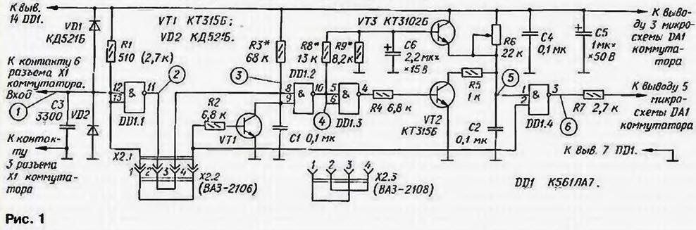
As rightly noted in the article by K. Kupriyanova, when administered in action octane-corrector described in [1]. there is a constant time the delay of ignition timing, proportional to the angular-on-year increase the rotational speed of the crankshaft of the engine with a subsequent abrupt increasing angle of OZ. Although in practice this phenomenon almost imperceptibly, internal reserves allow the source device to partially eliminate the mentioned the lag. For this purpose, in the device [2] it is enough to enter the transistor VT3, resistors R8. R9 and capacitor C6 (see diagram in Fig. 1).
(click to enlarge)
The algorithm octane-corrector qualitatively illustrated by graphs, it is shown in Fig. 2. The moments of the opening operation of the breaker contacts correspond plus surges from low to high - at the entrance octane-corrector (Fig. 1). In these moments there is a rapid discharge the capacitor C1 to almost zero through the open transistor VT1 (Fig. 3). Charging the capacitor relatively slowly through the resistor R3.
As the voltage on the charging capacitor C1 reaches the threshold switching logic element DD1.2. he transitions from a single state to zero (Fig. 4), a DD1.3 - in unit. Opening at this point the transistor VT2 quickly discharges the capacitor C2 (Fig. 5) to a level almost determined by the voltage on the base of transistor VT3. Since the delay switching element DD1.2 does not depend on the rotation frequency, medium voltage at its output increases with increasing frequency. The capacitor C6 averages is the tension.
Subsequent charging of the capacitor C2 through the resistor R6 begins with the specified level at the time of the closing of the transistor VT2. The lower initial the level, the longer it will take to charge the capacitor until the switch item DD1.4, which means that the longer the delay of spark formation (Fig. 6).
The obtained characteristic angle OZ is shown in Fig. 3, similar to Fig. 1 in the article by K. Kupriyanova, the curve 4. With the same initial conditions (tзад = 1 MS at N = 1500 min-1) control error in the most frequently used when the drive frequency interval of rotation of the crankshaft of the engine from 1200 to 3000 min-1 does not exceed 3 degrees.
It should be noted that the operation of this option octane-corrector depends significantly from the duty cycle of the input pulses. Therefore, it recommended establishing to collect the pulse shaper according to the scheme in Fig. 4. As you know, the pulses the Hall sensor of the car VAZ-2108 and its modifications have a duty cycle equal to 3, and the angle of the closed state of the contacts φзс contact breaker wazowski car is 55 deg., i.e. the duty cycle of the chopper "six" Q = 90/55= 1,63.
So you can apply the same pulse shaper for establishing octane-corrector different models of cars with only a small adjustment duty cycle, for contact of the ignition system recalculate the duty cycle based invert: Qинв = 90/(90 - φзс). or for VAZ-2106 Qинв= 90/(90 - 55)=2.57. Selecting the number of diodes shaper and a sinusoidal voltage generator signals, receive the necessary duty cycle at the input octane-corrector. In my practical option to obtain duty cycle 3 took four diode when the signal amplitude of the generator 5.7 V.
In addition to these, the shaper is suitable diodes series D. D, KD521, KD522 and the transistor KT315 with any letter index. You can apply the shaper pulses of a predetermined duty cycle and a different plan.
Concealer for car VAZ-2108 (inserted jumper x2.3 in Fig. 1) adjust as follows. Instead of the divider R8R9 temporarily connect any variable resistor group And a resistance of 22 ohms (engine to the base of the transistor VT3). First, the engine of the resistor is set at the extreme position, in which the base of the transistor "grounded". To the input of the corrector plug shaper, and to output oscilloscope.
Turn the power corrector and set the oscillator frequency of 120 Hz with the duty cycle of the output pulses of the generator equal to 3. Choose the resistor R3, achieving disable delay at this frequency. Then reduce the frequency generator to 50 Hz and dragging the slider of the resistor R6 alternately in both of the extreme the provisions define the maximum delay time of ignition timing, insertion octane-corrector (in our case 1 MS). Increase the generator frequency to 100 Hz and found that the position of the slider temporary variable resistor in which the maximum delay of the ignition timing set by the resistor R6. equal half maximum of 0.5 MS.
Now it is advisable to remove the dependence of the time delay of the ignition timing the frequency of the generator at the found position of the slider temporary variable resistor Count the frequency of rotation of the motor shaft in min-1: N = 30f. where f - the frequency of the generator. Hz. The angle OZ φоз = 6N·t, where t is the delay time, msec. The resultant angle φрез oz = 15 - φоз (see table) is applied to the graph of Fig. 3.
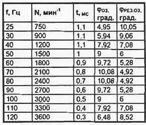
The form of the resulting graph should not differ greatly from curve 4, although numeric values may be others depending on the maximum time the delays. If necessary, repeat the adjustment operation.
After the establishment of temporary disable variable resistor, and by measuring resistance to his shoulders, solder fixed resistors with values closest to measured. It should be noted that the characteristic of the control system can significantly changed by varying the values of resistor R3 (the frequency of shutdown delay), divider R8R9 and capacitor C6. The initial conditions described adjust selected for comparison with the variant selected K. Kupriyanov: N = 1500 min-1, t = 1 MS, φмок = +15 deg. (φмок - angle mounted mechanical octane-corrector).
For use on the car VAZ-2106 octane-corrector establish similar (with jumper x2.3), but the pulses from the shaper must have a duty cycle of 2.57. Before installing the fluid on the car jumper x2.3 change in x2.2.
To finalize octane-corrector [2] his charge is removed from the switch 3620.3734 and mounted Assembly solder the transistor VT3 and the capacitor C6 so as to fee you can install to the old place. Matched resistors R8 and R9 soldered on the Board. Transistor V13 and the capacitor C6 should fix glue "Moment" or similar.
Instead CTB will fit any transistor in this series. The capacitor C6 - K53-4 or any tantalum or arsenomolybdate, suitable in size and the nominal value.
Literature
Author: E. Adigamov, Tashkent, Uzbekistan