


")

As is known, any security system, no matter how it was perfect, not will be able to meet the needs of all motorists. Therefore, in the process operation of autostorage described in the article "the Watchdog lock system ignition" in "Radio", 1999, No. 12, pp. 37-39, the author has introduced a number improvements dictated by real needs. These changes can to be included in the original version of the scheme completely or selectively, in accordance with the desires of the owner of the car.
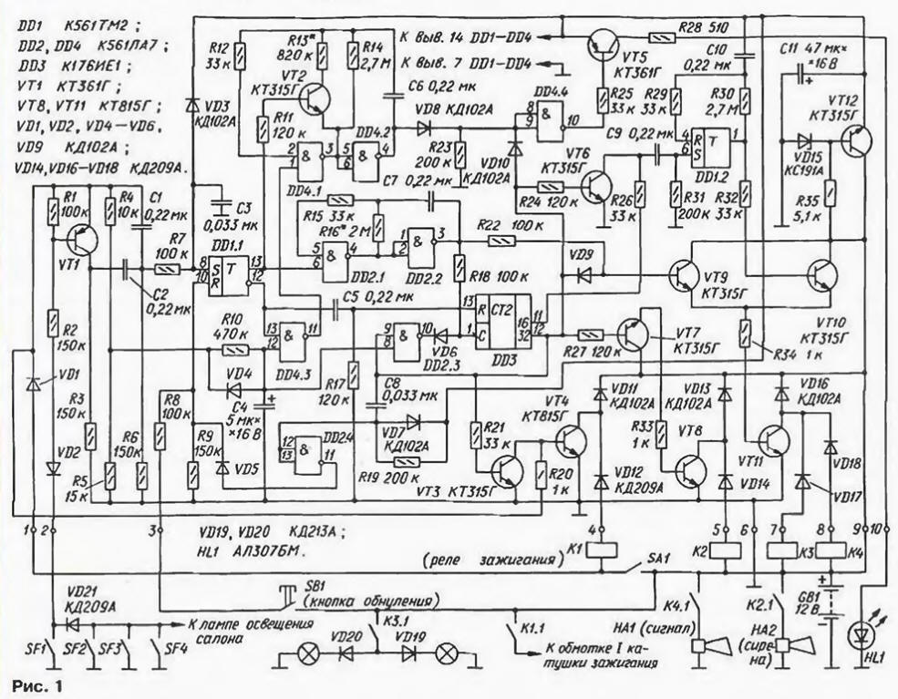
The locking scheme, containing all the changes shown in Fig. 1, and the sequence diagram work - in Fig. 2. Below are described only nodes watchman, distinguishing it from the source device.
(click to enlarge)
Let's start with changing the way alerts the driver to reset blocker. Instead of an audible alarm device used combo, including the led and the car's audio signal. In standby mode led HL1, mounted on the instrument panel flashes with a frequency of about 1 Hz (Fig. 2). that is indicative of the standby mode and at the same time "the first frontier guard, showing that the car is protected.
When the ignition frequency of the light is doubled, reminding the driver of the need of resetting the lock. In this state, the lock is not prevents starting of the engine.
If within 16 since the ignition is push a button SB1, the lock for a short time (0.5 s) will include the car's horn. Such a further reminder is particularly appropriate in a Sunny day, when the led can be difficult to see. Doubled the frequency of blinking LEDs there are still 16 after the beep.
In the case when after this time reset has not occurred, the led HL1 passes in a mode of continuous illumination, and the lock turns off the ignition and includes alarm (sound and light). Next, the algorithm works the lock still. But if a driver did pressed the control button SB1. the led goes out and the lock enters the mode of Movement is allowed."
In standby mode on the lower circuit on the input element DD4.3 there is a low the level is high (since the trigger DD1.1 is null state), and the output is high, permitting the operation of the generator on the elements DD4.1 and DD4.2 at a frequency of about 1 Hz. The rectangular pulse generator via diode VD8, the inverter DD4.4 and resistor R25 arrive at the base of the transistor VT5, which commutates the current through the led HL1.
When the ignition is on (contacts SA1) on pin 1 lock comes the supply voltage. The trigger DD1. 1 is switched, the input element DD4.3 is reversed, but its output remains high level, generator DD4.1, DD4.2 continues to work. However, the new transistor VT2 will double the frequency of the oscillator. Along with this high level with direct access the trigger will start the clock on the elements of DD2.1, DD2.2.
If at the time of the appearance in the fifth significant digit counter DD3 (output 16) high level on pin 3 lock reset pulse is not received, this high level through the resistor R26 is received in the differentiating circuit C9R31. She generates a pulse which triggers a single-shot. assembled on the trigger DD1.2 and with a cycle time of about 0.5 s. during this time the direct output the trigger will be a high level, the transistors VT10 VT11 and will be open and buzzer and lamps direction indicators. A short beep will be the second reminder of the need to stop the countdown supply reset pulse button SB1.
In the absence of a reset pulse for another 16 with the output of counter 32 DD3 you receive a high level.
which through the diode VD10 is transmitted to the input of the inverter DD4.4 and causes permanent the illumination of the led device goes into "Alarm". The ignition is switched off, and the alarm is enabled.
If during the first 32 with the cycle of operation of the lock at its output 3 goes changing the pulse, the trigger DD1.1 will return to the zero state and stop clock generator DD2.1, DD2.2. But at the inputs of the element DD4.3 will be to present a high level, and the output is low, which will stop generator DD4.1, DD4.2 and the cessation of illumination of the led HL1.
In the original version of the blocker was recommended as a siren alternative or Supplement the existing sound signal. Practice shows, the collaboration between the sirens and the signal does not increase the effectiveness of the lock, therefore, every car, understand the operation of the lock, to decide how it will be organized alarm. In according to this it will be clear what the load needs to be connected to the contacts of the relay and what elements on the Board can be mounted.
If, for example, will only work siren, don't need the diode VD18, but if only the signal, the extra elements will be VT7, VT8, R27. R33, VD13, VD14. If the owner believes that a visual alarm lamps will be more effective than lamps direction indicators, contacts K3.1 is connected to the headlight circuit using the same isolating diodes VD19. VD20. However, if your car headlights with halogen lamps, it is better to abandon the light-signalling lamps, as they consume very much power, and expensive to risk halogen lamps hardly worth it.
Some users blocker showed discontent. what. warming the engine before the trip, the door cannot be kept open (for example, for laying things or pick-up), as the lock keeps turning off the ignition. To address this deficiency in the chain of the door switches is introduced the separation diode VD21.
Now since the circuit SF1 switch driver door transistor VT1 opens and begins charging the capacitor C2. At this point, through the resistor R7 to the input S of the flip-flop DD1.1 receives a short pulse setting the trigger in one state. The resistance of the resistor R7 is reduced to 100 ohms with the. to pulse amplitude confidently reached a high level.
Thus, the diode VD21 lock does not respond to the position of the doors passengers. When driver's door is opened it triggers only once and after zeroing it can be left either closed or open. For mounting of the diode VD21 need to "infiltrate" in the wiring of the car.
The capacitor C3 in the original version the device is running "once in a lifetime" - connect the lock to the electrical system, it sets the trigger DD1.1 in a zero state. This capacitor is reasonable to exclude, and if at power on lock the trigger DD1.1 will be in a single state, it can be switched the reset button.
The. who has more satisfied with audible signal source variation we can recommend sound emitter - primer ZP-1 - move with PCB one of the panels of the casing of the lock from the inside, a signal will be better heard. For this purpose a wire rack, remove the cap and stick it with glue "The moment" through the annular foam pad height 3…Pre-4 mm. in the panel area of the cap bore holes with a diameter of 1.5… 2 mm.
You can take the cap off the lock. Each car seat for the primer can be selected individually. For example, in the VAZ-2109 - under plastic panel left-side rack (near the left seat belt), the volume of the warning signal will be sufficient.
To improve the secrecy of the lock voltage of high level is supplied to the reset button can not be removed with positive power wire, as shown in the scheme, and, for example, with the lamp brake light. In this case, before reset blocker, you will need to press on the brake pedal.
The installation location in the vehicle relay ignition is well known to any the motorist, even not very experienced. Therefore, if the blocker is disabled not this relay, and the other additional associated with relay ignition Executive chains, guard the effect will be more significant. Here great scope for creativity, but we should not forget that contactless ignition system do not tolerate improper interference.
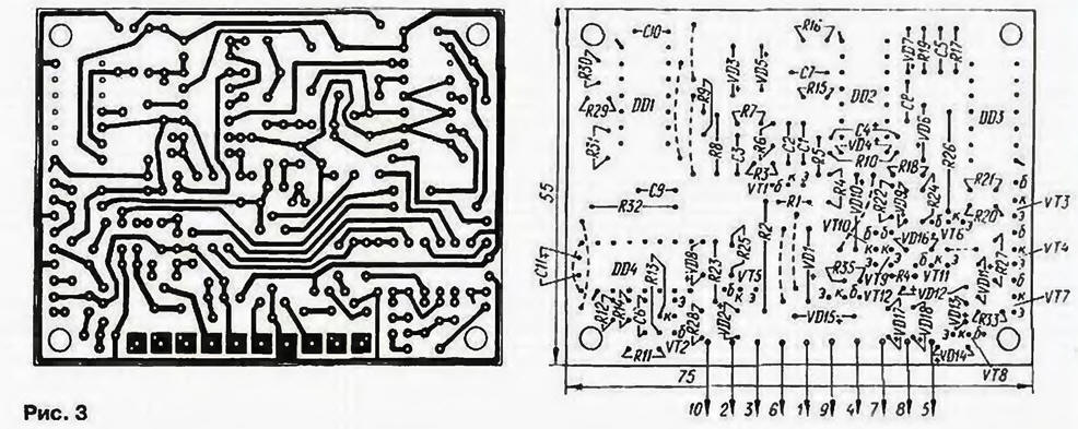
Drawing of the PCB of the new version of the blocker is presented in Fig. 3.
In conclusion, we note that the lock has been tested on different cars in for several years and proved to be quite reliable device. However, not be superfluous to warn that the excellent work of the lock is possible only with the reliability of the electrical system. So. for example, on a twelve year old the Mazda car-626 run blocker, not only when the ignition is switched key, but when it was switched off. "Guilty" was the lock - pin the group had considerable wear. As a result bounce contacts when the ignition lock was run again.
Author: Sergei Ryzhkov, Bishkek, Kyrgyzstan