Describes sources of radio interference from the ignition system, shows how noise suppression, ignition system recommended by the filter on the food chain radio equipment.
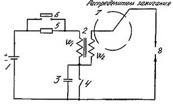
In the ignition system of an internal combustion engine on petrol four main a source of electromagnetic oscillations: a primary circuit, a circuit contact breaker, circuit distributor and spark plug. The last three belong to high-frequency sources of electromagnetic radiation within the range of radio broadcasting. For clarity, we consider the so-called "classic" ignition system, invented 100 years ago and have not changed much so far, is shown in Fig.1.

Fig. 1: 1 - battery; 2 - ignition coil; 3 - condenser irogami"; 4 - the contact-breaker (now it is most commonly used transistor); 5 - additional resistance to limit the current of the coil in normal mode work); 6 - contact shunt additional resistance to increase 5 the ignition voltage for the period of starting the engine; 7 - the ignition distributor; 8 - spark plugs (number of cylinders).
The first source of radio - contact-breaker 4 at the moment when he opens. The second source is the bit interval of the ignition distributor 7 during its breakdown. The third source breakdown candles 8.
Radiation of electromagnetic waves in space is determined not only power generator, but also radiating circuit, and galvanic induction bonds. For example, the battery being the common power supply all consumers in the vehicle, causes a current connection between consumers. Classic ideology of providing noise immunity determines the need to suppress interference, primarily in the source of interference, and then the inputs of consumers.
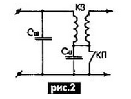
Based on this concept, to exclude high-frequency circulation electromagnetic oscillations in the circuit ignition coil - battery - circuit the inclusion of the ignition system, you must install the bypass capacitor the input circuit of the ignition coil, as shown in Fig.2.

As can be seen, the presence of a shunt capacitor will create for electromagnetic oscillations of fundamental frequency "short" way that will simultaneously improve conditions the formation of the high-voltage pulse and will serve as a filter for the high-frequency part of the spectrum interference from the contact breaker and high-voltage the chains.
The value of shunt capacitance is chosen from the condition: SS"si. Since the nominal capacity usually lies in the range 0.15...0.3 UF 2 UF would be sufficient.
In existing systems in high-voltage ignition parts taken measures to suppress radio interference. For example, in the dispenser installed resistor, and in some systems, connecting high-voltage wires have conductive mine alloy with a high ohmic resistance. All of these activities significantly reduce interference by increasing the attenuation of electromagnetic waves. A very effective way to suppress interference shielding is high voltage circuits instead of introducing them in the damping resistors. The thing that initially high-voltage circuit was performed shielded. Now aviation systems and vehicles with radio communication equipment still use only shielded high-voltage wires in the ignition systems.
We can assume that the events unfolded like this. First, when there is no interference very bothered, someone suggested that to save money by removing the screens from the wires. Then, when the noise became annoying and people are smarter in the field of electromagnetic hesitation, again there was an inventor who introduced the damping resistance, then started enhancements like to do resistance and where to place them.
Shielding of high-voltage, especially chart wires, leads to a significant effectiveness of ignition of the fuel-air mixture by increasing the energy of the electric discharge in the chart with the transformation period in multi-frequency impulse.
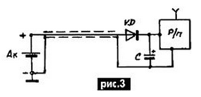
Now for the filter in the power supply circuit of the radio. Known filters based on various combinations of inductors and capacitors. The proposed filter is called "diode" and is a half-wave rectifier with capacitive the filter, as shown in Fig.3.

Here: AK - battery; VD is the diode on any current 0,5...1,0 A reverse voltage of at least 50 V; C - condenser electrolytic any brand with a capacity of at least 500 μf, for a voltage not less than 25 V.
The radio connects to the battery with shielded wire with attach the screen to the "mass" at the connection point sub-zero output of the battery. Shielded wire should be outside in isolation (cable type RK), and the radio housing should not touch in the seat of the metal structural members of the chassis of the vehicle.
Author: T. A. Belyavsky, Cherkassy


