This design can be recommended prepared hams who already have experience making simple blocks the ignition and wish to have a device, from which, figuratively speaking, "squeezed out" all of today's seeming possible. Over the years, a stable ignition module [ 1 ] repeated many auto and hams, and despite the identified shortcomings, we can assume that it is the test of time held. It is also significant that in the literature until the publication of similar simplicity of the designs with the same parameters. These circumstances prompted the author to make another attempt to fundamentally improve the performance of the unit, while maintaining its simplicity.
The main difference of the improved ignition module [ 1] is a notable improvement in its energy characteristics. If the original block maximum duration sparks did not exceed 1.2 MS, and it could be obtained only at the lowest frequency of sparking, the new duration of the spark is constant in the entire operating band 5...200 Hz and equal to 1,2...of 1.4 MS. This means that on the average and maximum engine speeds - and this is the most commonly used modes - the duration of the spark is largely consistent with the current requirements.
Changed considerably and the power supplied to the ignition coil. At a frequency of 20 Hz when the coil B 115 it reaches 50...52 MJ and 200 Hz to about 16 MJ. Enlarged the limits of the supply voltage, in which the unit is operable. Confident scroobious when the engine is provided at a vehicle voltage of 3.5 V, but the functionality of the unit is kept at 2.5 V. the maximum frequency of the spark is not broken, if the supply voltage is 6 V, and the duration of the spark is not less than 0.5 MS. . These results were obtained mainly due to the change of the mode of operation of the Converter, especially in terms of its initiation. These figures, which, according to the author, there are practical limits when using just one transistor, there is also the use of the ferrite magnetic core in the transformer.
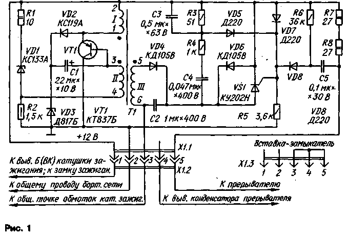
As can be seen from the schematic diagrams of the block shown in Fig.1, the main changes relate to the Converter, i.e. the generator charging pulse source of the storage capacitor C2. Simplified circuit of the Converter start, made, as before, by the scheme of a single-stable blocking oscillator. Functions starting bit and diodes (VD3, respectively and VD9 under the old scheme) now performs one Zener diode VD1. This solution provides a more reliable starting of the generator after each cycle of sparking by a significant increase in the initial bias on the emitter junction of transistor VT1. This is not lowered nevertheless, the overall reliability of the unit as a mode transistor on any of the parameters did not exceed permissible values.
Changed and charging circuit delay capacitor C1. Now he is after charging the storage capacitor is charged through the resistor R1 and Zener diodes VD1 and V03. Thus, stabilization are two of the Zener diode, a total voltage which when open and is determined by the voltage level on the storage capacitor C2. Some increase in the voltage on this capacitor is compensated by a corresponding increase in the number of turns of the underlying winding of the transformer II. The average voltage level on the storage capacitor is reduced to 345 365...In that increases the overall reliability of the unit and is responsible, along with the required power sparks.

In a discharge circuit of the capacitor C1 is used стабисторVD2, allowing to obtain the same degree of overcompensation when reducing on-Board voltage, as three or four ordinary serial diode. Upon discharge of the capacitor, the Zener diode VD1 is open in the forward direction (like a diode VD9 of the original block).
The capacitor NW provides an increase in the duration and power of the pulse, which opens SCR VS1. This is particularly necessary when the frequency of sparking when the average voltage level on the capacitor C2 is significantly reduced.
In blocks electronic ignition with multiple discharge the storage capacitor to the ignition coil [1,2] the duration of the spark, and to some extent its capacity determines the quality of the SCR, since all oscillation periods, except the first, are created and maintained only by the energy storage device. Less than the energy costs for every inclusion of SCR, the greater the number of launches will be possible and the more energy (and more time) to be transmitted to the ignition coil. Therefore, it is highly desirable to choose the SCR with a minimum opening current.
Good can be considered as SCR, if the unit provides start sparking (with a frequency of 1 ...2 Hz) when the power supply voltage of 3 V. Satisfactory work quality meets at a voltage of 4...5 V. With a good SCR duration sparks equal to 1.3...1.5 MS, with a bad - is reduced to 1...1.2 MS. In this case, as it may seem strange, power spark in both cases is approximately the same due to the limited capacity of the Converter. 8 in the case of a longer duration, the capacitor drive is almost completely discharged, the initial (or average) level of the voltage on the capacitor is set by the Converter, is somewhat lower than in the case of shorter duration. With less duration initial level higher, but the high and the residual voltage on the capacitor due to its incomplete discharge. Thus, the difference between the initial and final voltage levels on the drive in both cases are almost identical, and from it depends the amount injected during the ignition coil energy [R]. And yet, for a longer duration spark leads to better combustion of the combustible mixture in the cylinders of the engine, i.e. increases its efficiency.
In normal operation, block the formation of each spark correspond to 4.5 period of oscillations in the ignition coil. This means. the spark is a nine alternating discharges in the spark plug, continuously one after the other. Cannot therefore agree with the view (described in [4]) that the contribution of the third and especially the fourth of the oscillation period is not detected under any conditions. Actually each period contributes very specific and tangible contribution to the total energy of sparks, as confirmed by other publications, for example [2]. However, if the on-Board voltage source connected in series with the circuit elements (i.e. consistently • with the ignition coil and accumulator), strong attenuation, insertion it is the source, and not other elements, indeed, does not allow to detect the above-mentioned contribution. Such inclusion and used in [4].
In the described unit source cutoff voltage in the resonant process does not participate and mentioned losses, of course, does not make.
One of the most critical components of the block transformer T1. The magnetic core Sh made of occifer NM. The coil 1 comprises a coil 52 of PEV-2 0,8; 11-90 turns of wire sew-2 0,25; III - 450 turns of wire sew-2 0,25.
The gap between the W-shaped portions of the magnetic circuit should be kept as accurately as possible. To do this in the Assembly between its extreme rods are placed without glue laminated bakelite (or textolite) strip thickness of 1.2+0.05 mm, after which the components of the magnetic pull together strong thread.
Outside the transformer must be covered with several layers of epoxy resin, nitroblue or the nitro enamel.
The coil can be performed on a rectangular spool without cheeks. The first winding is wound III, in which each layer is separated from the next with a thin insulating seal, and complete the three-layer gasket. Next, the winding is wound II. The winding 1 is separated from the previous two layers of insulation. The edges of each layer during winding on the spool should record any microclean.
Flexible coil leads are best made at the end of the winding. Output ends of the windings 1 and II should be in the direction diametrically opposite ends of the winding I, but all conclusions should be on one end of the coil. In the same manner and have flexible findings that fixed thread and glue on a strip of insulation (panel Board). Before pouring the conclusions of the mark.
Except KUN, in the block can be applied SCR CU with an alphabetical index A-G In the choice of SCR should take into account that, as experience shows, CAN compared to CU have in most cases less current open-tion, but more critical to the parameters of the trigger pulse (duration and frequency). Therefore, for the case of the use of SCR from CU the values of circuit elements lengthening the spark you need to adjust the capacitor NW should have a capacity of 0.25 microfarad, and resistor R4 is the resistance of 620 Ohms.
Transistor CT can be any alphabetic indices, except for W, I, K, T, U, F. it is Desirable that the static current transfer ratio was not less than 40. The use of a transistor of another type is undesirable. Heat sink transistor must have an effective area not less than sm. The role of a heat sink is convenient to use a metal casing of the unit or its base, which should Supplement the cooling fins. The casing must ensure that the splash block.
The Zener diode VD3 must also be installed on a heat sink. In the unit it represents two bands of sizes HH mm, bent U-shaped and nested one in another. Zener DB you can replace the series circuit of the two Zener LW16В; when a vehicle voltage of 14 V and a frequency of scrooby-tical 20 Hz this pair should provide the drive voltage 350.. .360 V. Each of them is mounted on a small heatsink. The Zener diodes are selected only after the selection and installation of SCR.
The Zener diode VD1 selections not required, but it must be in a metal enclosure. To increase the overall reliability of the unit it is advisable that the Zener diode to provide a small teplootvodom the swage form of a strip of thin aluminum.
Stabistor XA (VD2) can be replaced by three diadama DA (or other silicon diodes with pulsed direct volume not less than 0.5 A), connected in series. Most parts of the unit are mounted on a printed circuit Board of foiled fiberglass 1.5 mm thick. a Drawing Board shown in Fig.2. PCB designed in regard to the possible installation of parts for various replacement options.
For the unit, designed to work in areas with harsh winter climate, oxide capacitor C1 is desirable to use tantalum with an operating voltage below 10 V. It is installed instead of a big jumper on the motherboard, and the connection point of aluminum oxide capacitor (it was shown on the Board), suitable for the vast majority of climate zones, it is necessary to close the jumper corresponding length. The capacitor C2 is MBGO.MBGC or K73-17 on voltage 400...600 V.
If selected for the block of SCR from CO bottom in Fig.2 part of the payment should be adjusted as shown in Fig.3. When mounting the SCR should one of the screws fixing it to be separated from the printed track common wire,
The health check, and the more the adjustment should be carried out with such an ignition coil with which the unit will operate in the future. It should be borne in mind that the unit is switched on without the ignition coil, loaded igniting a candle, is totally unacceptable. To check it is enough to measure peak voltmeter the voltage on the storage capacitor C2. This voltmeter can serve avometr having a limit DC voltage of 500 V. Avometr connected to the capacitor C2 through the diode DB (or similar), and clamps avometra shunt capacitor 0,1 .0.., 5 UF voltage 400...600 V.
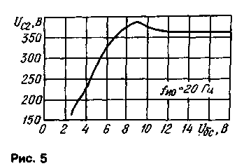
At nominal supply voltage (14 V) and the frequency of sparking 20 Hz, the voltage at the drive must be in the range of 345 365...V. If the voltage is less, first of all choose the SCR with the foregoing. If after compilation will be provided skroob education by lowering the supply voltage to 3 V, but on the capacitor C2 at a nominal voltage litany will be high voltage, you should choose a Zener diode VD3 with a somewhat lower voltage stabilization.
Next, check the unit on the highest frequency of scroobious (200 Hz), supporting the nominal vehicle voltage. The voltage on the capacitor C2 must be within 200 185...In and consumed by the current block after continuous operation for 15...20 min should not exceed 2.2 A. If the transistor at this time is heated above 60°C at room ambient temperature, heat sink surface should be slightly greater.


The capacitor NW and resistor R4 selections usually do not require. However, for individual instances of triacs (as both and other type) may need to be adjusted to the nominal if frequency of 200 Hz is detected instability in the earth. It usually manifests itself in the form of a transient fault in the voltmeter connected to the drive, and noticeable to the ear.
In this case it is necessary to increase the capacitance of the capacitor NW 0,1...0,2 µf,and if that doesn't help, return to the previous value and increase the resistance of the resistor R4 100...200 Ohm. One of these measures, and sometimes both together, usually eliminate the instability of the run. Note that the increase in the resistance decreases, and the increase in capacity increases the duration of the spark.
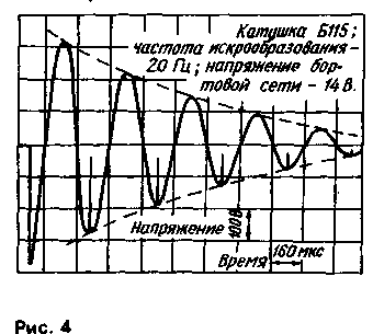
If it is possible to use the oscilloscope, it is useful to ensure the normal flow of oscillatory process in the ignition coil and its actual duration. Until complete attenuation must be clearly visible 9-11 of half wavelengths, the total length of which should be equal to 1.3...1.5 MS for any frequency of scroobious. The input X of the oscilloscope should be connected to the common point of the windings of the ignition coil.
A typical view of the waveforms shown in Fig.4. Bursts in the middle of the negative half waves correspond to single pulses of the blocking oscillator when the direction of current in the ignition coil.
It is advisable to check the dependence of the voltage on the storage capacitor from the on-Board voltage. Its appearance should not be significantly different from those shown in Fig.5.
Made the unit should be installed in the engine compartment in the front, cooler parts. Irogami capacitor breaker disconnect and connect its output with the corresponding contact of the power connector X1. The transition to the classical ignition is performed, as in previous designs, the installation of the insertion of the contactor X1.3.
In conclusion, we note that attempts to obtain as long a spark with transformer on steel magnetic core, even steel of the highest quality, will not lead to success. The maximum duration that can be achieved - 0,85 0,8...MS. However, the unit is almost unchanged (the resistance of the resistor R1 should be reduced to 6-80m) functional and transformer steel magnetic circuit with said winding characteristics, and performance of the unit is higher than its prototype [1].
Literature
Author: G. Karasev St. Petersburg; Publication: N. Bolshakov, rf.atnn.ru


