


")

Economic, power and operating parameters of the engine of the car largely depends on the proper installation of the ignition timing (03). Factory setting angle of 03 is not suitable for all cases, and therefore we have to adjust by finding a more accurate value in the zone between the point of detonation and a noticeable reduction in engine power.
It is known that the deviation from the optimum angle of OZ at 10 degrees, the fuel consumption may increase by 10 % [1 ]. Often required to significantly change the initial angle of OZ depending on the octane number of gasoline, the air-fuel mixture and actual road conditions. A disadvantage of the used cars centrifugal and vacuum regulators is the inability to adjust the angle of OZ with the driver's seat while driving. As described below, the device allows for such adjustment.
From similar to destination devices [2, 3, 4] electronic corrector is simple schemes and a wide range of remote setting the initial angle of OZ. Concealer works in conjunction with centrifugal and vacuum regulators. It is protected from the effects of contact bounce of the switch and interference from the vehicle network. In addition to the correction of the angle of OZ, the device allows to measure the rotational speed of a crankshaft of the engine. From digital corrector [5] described provides a smooth adjustment of the angle of correction, contains fewer parts and is simpler to manufacture. Main technical characteristics The supply voltage. 6 17… Current consumption when the engine is not running. And, when the closed breaker contacts 0,18 when you open contacts of the breaker 0,04 The frequency of the trigger pulses. Hz… 3,3…200 Installation starting angle of OZ in the dispenser, hail.... '20 The limits of distance correction angle OZ. hail........ 13…17 Pulse duration delay, MS: most.... 100 lowest.. ,. 0,1 The duration of the output pulse switching, MS........ 2.3 The maximum value of the output switched current. And 0.22… Engine operation at set angles specified by the corrector, is possible in the case, if the pulse from the circuit breaker delayed for a while
T3=(FR-FC)/6n=(FR-FC)/180*Fn
where FR, FC - starting angle of OZ, mounted dispenser and proofreader, respectively; n is the rotational speed of a crankshaft; Fn=n/30, the frequency of sparking.
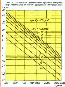
Fig.1
In Fig. 1 in the logarithmic scale shows the dependence of the length of the time delay of sparking from the rotational speed of the crankshaft computed for different values of the initial angle OZ, set the concealer. This schedule is useful when establishing and calibrating the device.
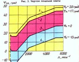
Fig.2
In Fig. 2 illustrates the characteristics and the limits of change of the current value of the angle OZ depending on the rotational speed of the crankshaft of the engine. Curve 1 is shown for comparison and illustrates this relationship for a centrifugal regulator during initial installation angle OZ, equal to 20 degrees. Curves 2, 3, 4 - result. They are obtained when combined centrifugal regulator and electronic corrector at set angles 17, 0 and -13 deg.
Corrector (Fig.3) consists of a start node of the transistor VT1, waiting two multivibrators transistors VT2, VT3 and VT4, VT5 and the output key on the transistor VT6. The first multivibrator generates a pulse delay of sparking, and the second transistor controls the key.
Fig.3 (click to enlarge)
Suppose that in the initial state of the breaker contacts are closed, then the transistor VT1 of triggering unit is closed. Forming the capacitor C5 in the first multivibrator is charged by the current through the emitter junction of transistor VT2, resistors R11, R12 and the transistor VT3 (charging time of the capacitor C5 can be adjusted by resistor R12). Forming a capacitor C8 of the second multivibrator will also be charged. Since the transistors VT4 and VT5 opened, VT6 will also open and close the output Breaker of the ignition module via a resistor R23 to the housing.
Upon opening the breaker contacts of the transistor VT1 is opened and VT2 and VT3 are closed. Forming the capacitor C5 begins to recharge through the chain R7R8R14VD5R13. The parameters of this circuit are chosen so that recharging of the capacitor is much faster than charging. Reload speed is controlled by resistor R8.
When the voltage on the capacitor C5 reaches a level at which to open the transistor VT2, the multivibrator returns to its original state. The more often the unlocking of the breaker contacts, the to a lower voltage charging the capacitor C5 and the less will be the duration of the pulse generated by the first multivibrator. This is achieved inverse relationship between the delay time of sparking and the rotational speed of a crankshaft of the engine.
The decline of the pulse generated by the first multivibrator through a capacitor C7 runs the second multivibrator. It generates a pulse of about 2.3 MS. This pulse closes the transistor switch VT6 and disables the clip "Breaker" from the body and thereby simulates the opening of the breaker contacts, but with a delay of time t, determined by the width of the pulse generated by the first multivibrator.
HL1 led informs about the passage of the pulse from the sensor-breaker via electronic corrector to the ignition module. Resistor R23 protects the transistor VT6 at casual connect its collector to the positive wire to the vehicle network.
The unit is protected from contact bounce breaker provides the capacitor C1, which creates a time delay (about 1 MS) closing of the transistor VT1 after the circuit breaker contacts. Diodes VD1 and VD2 prevent discharge of the capacitor through the circuit breaker and compensate for the voltage drop that occurs on the conductor connecting the engine with the vehicle body when the starter motor, which increases the reliability of electroyogi corrector during start-up of the engine. From interference and the onboard network, the device protects the circuit VD8C9, Zener VD6, VD7, resistors R2, R6, R15, and capacitors C2, C3, Sat.
The rotational speed of a crankshaft measuring circuit VD9VD10R25R26PA1. The scale of the tachometer linear, since the voltage pulses at the collector of transistor VT5 have a constant duration and amplitude provided by the Zener diode V07. Diodes VD9, VD10 eliminate the influence of residual stress on the transistors VT5, VT6 for tachometer readings. The rotational speed of the ticks on the scale of the milliammeter PA1 with the current full deflection 1…3 mA.
In the corrector used capacitors K73-17 - C1, C8, C9; K53-14-C2, C5; K10-7 - C3, C6; KLS - C4. C7. Resistor R8 - SDR-12A, R12 - GPA-6, R23 is composed of two resistors MLT-0,125 resistance of 10 Ohms. Diodes KD102B KDA can be replaced with any of a series of CD or CD; CDA - KD522. CD, CD, CD, D - with any letter index. Zener XA, DE can be replaced with Other suitable power voltage stabilization. Transistors CTG can be replaced by KT315B, CTV, CTA, CTB; KT361 MR. CTB, CTV, CTB, CTG; CTV - CTA, CTB.
Parts of the device are mounted on a printed circuit Board of foiled fiberglass with a thickness of 1 mm. drawing of the PCB and the arrangement of parts therein shown in Fig. 4.
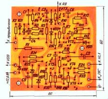
Fig.4
For adjustment of the device requires a supply voltage of 12…14 V, calculated at the load current of 250…300 mA. Between the conductor from the resistor R23 and the positive output of the power source on the setup time is connected by a resistor 150… 300 Ohm with power dissipation of 1-2 watts. The input device connect the simulator circuit of an electromagnetic relay. Use open pair of contacts; one of them is connected to the common point of resistors R1, R2, and the other to GND. The relay coil is connected to the generator to provide a relay switching with a frequency of 50 Hz. In the absence of the generator relays can be powered from a step-down transformer is plugged in.
After power on check the voltage at the Zener diode VD6 - it must be of 6.8 V. If the corrector is assembled correctly, when running simulator breaker HL1 led should be on.
In parallel to the transistor VT3 is connected with a DC voltmeter with a scale for a voltage of 2…5 Vis the current full deflection of not more than 100 μa. The engine output resistor R8 and the far right. When running the simulator breaker trimming resistor R12 on the scale voltmeter set the voltage to 1.45 V. this voltage pulse duration delay should be equal to 3.7 MS, and the initial angle of 03 is equal to -13 deg. In the middle position of the slider of the resistor R8, the voltmeter should show a voltage of 1 V, which corresponds to zero initial corner of the LAKE and in the left-0.39 In - 17 degrees (see tab.1).
Table 1
FC
hail
17
15
10
5
0
- 5
-10
-13
t3
MS
0,33
0,56
1,1
1,7
2,2
2,8
3,4
3,7
IKE.VT3
In
0.39
0,46
0,64
0,82
1
1.16
1,34
1,45
The most simple (but not perfectly) concealer it is possible to establish the following way. The engine of the resistor R12 is set to the middle position, and the engine of the resistor R8 is rotated one third of a full rotation angle from the position of minimum resistance. Turning the distributor housing ignition on 10 degrees in the direction of the earlier ignition (against the motion of the shaft), start the motor and resistor R12 achieve a steady idle. For calibration of the scale controller starting angle of the automotive strobe.
Tachometer graduate tunable resistor R26 (at a frequency of trigger pulses 50 Hz the needle of the microammeter must show 1500 min '). If the tachometer is not needed, its elements can not to mount.
To connect corrector and convenient for the driver to place five-pin socket (CP-SH-4-5/16-R), the contacts of which are output conductors from the electrical system, circuit breaker, block plug, housing and tachometer (if provided). The corrector is mounted in the casing, installed in the vehicle, for example, near the ignition switch.
Concealer can be used together with the electronic ignition unit, described in [6]. It can work with other trinistorny ignition systems with both pulsed and continuous accumulation of energy on the capacitor. Thus any modification in blocks of ignition associated with the installation of the corrector, as a rule, is not required.
Literature
Author: V. Bespalov, Kemerovo; Publication: N. Bolshakov, rf.atnn.ru