Block 25.3763 control glow plug of the production of JSC "NPPP "ELARA" mounted on cars VAZ-21045 with a diesel engine VAZ-341 production of JSC "Korabel co.. It is designed to enable candles 1602.3740, ensure the ignition of the fuel-air mixture when starting of the motor.
The algorithm works as follows: when the key is in the ignition transferred from position "Off" to "Ignition", the glow plugs installed one in each cylinder, are connected to the battery. At this point the warning light on the dashboard of the car. After time interval tnn called preheating time, the warning light goes out, indicating the willingness of the engine to start. After this glow plugs remain energized additionally, within 5 seconds.
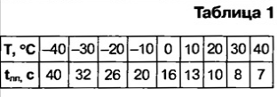
When the starter motor candles are switched on and off 5 seconds after turning off the starter. The preheating time tnn is a function of the temperature in the engine compartment of the vehicle (sensor temperature is mounted directly on the circuit Board of the control unit), the corresponding values tnn given in table. 1.

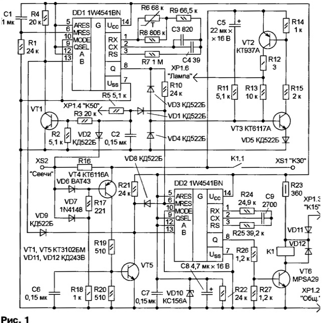
The scheme of the control unit shown in Fig. 1. Reference designators all elements match the schema of the manufacturer. The main functional the nodes of the block - two timer collected on chips 1W4541BN (DDI, DD2), the source the power indicator lights in the transistor VT2, VT3, the node short circuit protection. the circuit of the supply to the glow plug transistors VT4, VT5 and node switching on the transistor VT6 and relay K1.

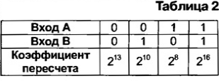
Chip 1W4541BN - programmable timer with a built-in generator, frequency oscillations which define an RC circuit connected to the terminals of RX, CX and RS. The conversion factor is determined by the ratio of the signals at the inputs A and b (tab. 2).

When the ignition is switched to the contact HR.3 control unit receives the vehicle voltage of the vehicle's +12 V. the Diode VD11 protects the unit against polarity reversal of the supply voltage, stabilizer stabilizes voltage R23VD10 power supply ICS DD1, DD2 at 5.5 V, which enables the unit control in the range from 6 to 16 according to the requirements of AVTOVAZ.
The circuit R1C1 DD1 starts the timer, the output Q which there is a single the signal at the output Q of the chip DD2 is also set high level, which turns on transistor VT6 and relay K1. Closing contacts relay K1 V23071-A1009-A132 from SIEMENS designed for connecting a load with the current consumption 120 A and the off - current of 70 A. the Relay is mounted directly on the circuit Board of the control unit. It has no analogues with the same dimensions. The voltage from the battery (contact CSA" connection XS1) through contacts K1.1 and current sense resistor R16 comes the glow plugs.
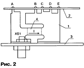
Resistor R16 is made of nichrome sheet thickness of 1 mm, its location in the control unit shown in Fig. 2 (1 - resistor, 2 - printed circuit Board with elements 3 to the base unit 4 - measuring track). The measured current (I proceeds from the connection XS1 "C" to the contacts b, C, D. the Contacts A and E - the measuring. The resistance of the resistor R16 is determined by the length of the track 4 and can to be adjusted by changing the length of the lateral grooves. If the current I exceeds set threshold 175 And sequentially opened transistors VT4, VT5 and the inputs To circuits DD1, DD2 focused on a common wire, then the output Q timer DD2 set to low level and the transistor VT6 off. Relay opens the contacts K1.1 power circuit.

In the normal mode after switching on the ignition and closing the contacts K1.1 pulse current through the circuit C5R11 opens the transistor VT3, and then VT2 - source included the power indicator lights. Resistor R12 limits the current through the cold spiral the lamp at the time of inclusion. The timer DD1 generates a time interval prior heating tnn. The temperature dependence of the frequency of the internal oscillator chip DD1 defines the thermistor R6 232264063683 PHILIPS. Capacitor C4 - adjusting for initial setup time tnn at a temperature of 20 °C. At the end of time tnn at the output Q of the timer DD1 appears low and the timer starts and the DD2 forming time interval 5, at the same time the warning light on the instrument panel turns off. 5 with the transistor VT6 and relays K1 is turned off and the candles are deenergized.
When the starter motor with a voltage of +12 V is supplied to the contact HR.4 "C50", timer DD2 will be enforced in its original condition and the relay K1 is activated. After turning off the starter candles remain energized for 5 s and off. Rerun the preheating of the glow plug is only possible after turning off and on the ignition. In the case of circuit warning lamp the transistor VT3 is closed and the lamp is de-energized.
The control unit is housed in a plastic housing on the basis of which is the four-pin pin header for connection of low voltage circuits. Power contacts of the control unit screw, the connection XS1 is threaded MB, XS2 - M5. A printed circuit Board installed in the block elements inside. The unit is secured in the engine compartment of the vehicle through the intermediate bracket. All the elements are designed to work in temperatures ranging from -40 to +85 °C Drop the voltage on the switching contacts must not exceed 20 mV at 1 A current load.
Author: P. Vasiliev, Cheboksary


