


")

The above-described device is intended for use in the garage, when the repair of the engine. In the further operation of the vehicle occurs the gradual increase of backlash in the drive mechanism of the interrupter-distributor the wear of the Cam and the sliding contact pads, electroerosion contacts, etc. And only when an error occurs in the engine usually remember about the angle of the legislative Assembly.
It is known that the deterioration of engine performance becomes noticeable when "care" angle KYC ±5…7% of its optimal value. This fact allows to equip the car with a simple indicator, promptly informs the driver approaching the moment when the angle KYC will go beyond established limits.
Diagram of the indicator is shown in Fig. 3.
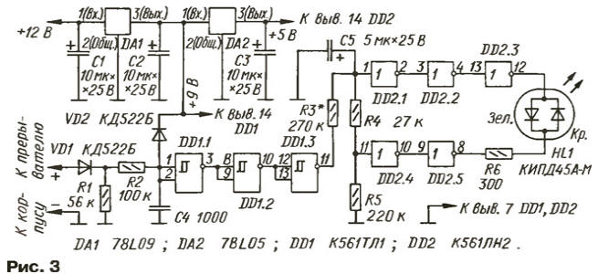
The device allows to control the angle KYC in the range of 30 to 60 degrees. which is sufficient for most domestic cars. Specific angle limits set in the process of building. When specified on the diagram the values of angle details corresponds to the value of 55 ±3 deg, (for cars VAZ).
On the elements of DD1.1-DD1.3 assembled shaper rectangular pulses, and the resistors R3-R5 and elements DD2.1-DD2.5 - dual-channel threshold device. At each opening of the breaker contacts plus the voltage drops to the input element DD1.1, inverter included. The duration the closed state of the breaker contacts is equal to the pulse duration high level at the output of this element.
After passing through the buffer elements DD1.2 and DD1.3, rectangular pulses the voltage divider R3-R5, which entered the integrating capacitor C5. Since the elements of the IC DD1 feed stable voltage (9 V), the amplitude of the pulses is constant in any mode of operation of the engine.
The capacitor C5 is formed a constant voltage proportional to the duty cycle of the pulses from the circuit breaker, i.e. proportional to the angle of the legislative Assembly. Choice of the values of resistors R4, R5 set the voltage levels corresponding to controlled angle.
Channel threshold device that controls the lower limit, assembled on inverters DD2.1-DD2.3, and the top - DD2.4, DD2.5. The outputs of both channels loaded shared bicolor led HL1. To expand the interval of the controlled voltage in the lower side is provided by the power of the chip DD2 from pyativolnovye stabilizer DA2.
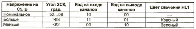
Resistors R3-R5 are selected such that, when the voltage at the capacitor C5 corresponds to the optimal value of the angle of the legislative Assembly, at the input of the inverter DD2.1 was a high level, and the input of the inverter DD2.4 - low. The outputs channels will be low the led is off.
If you reduce the high voltage level at the input of the inverter DD2.1 will be replaced low, and the input of the inverter DD2.4 will remain the same. Therefore, the output inverter DD2.3 will be level 1, and the output will remain zero - indicator HL1 will Shine green.
It is easy to see that the result of an increase in voltage above a nominal will be the red glow of the indicator. Compliance voltage levels of the input and output codes canals and color of the light is reflected and the table.
Consider the order of calculation of the values of resistors R3-R5.
The maximum angle KYC (theoretical value, as this contacts permanently closed, the spark is missing) for four-cylinder the engine is equal to 360 deg.: 4 = 90 deg. This angle would correspond to DC voltage 9 output driver (output element DD1.3). The minimum angle KYC (also theoretical - contact constantly open, sparking is not) equal to zero; the voltage at the output of generator close to zero.
This allows you to take intermediate values of the angle is equal to the corresponding output voltage multiplied by ten: 9 - 90 deg., 5 In - rd., 1 In - 10 deg. Calculate the resistor values for zone control 52…58 deg. The zone boundaries correspond to the voltage values of 5.2 and 5.8 V. the Threshold voltage Unop for inverters chip K561LN2 equal UnfcTT/2 = 2.5 V.
Let us set a minimum current through the circuit of resistors R3-R5 divider Un = 0.01 mA. Then Rобщ = R3 + R4 + + R5 = Umin/Imin = 5,2/0,01 = 520 ohms. Maximum current through a divider lmax = Umax/Rобщ = 5,8/520 = 0,0112 mA.
Hence, R5 = Unop/lmax = 223 K;
R4 + R5 = Unop/lmax = 250 ohms;
R4 = 250-223 = 27 kω;
R3 = Rобщ - (R4 + R5) = 270 ohms.
The estimated pick up the nearest values of the resistors of the divider. So the same way to calculate the resistor values for the other boundaries of the zone of control.
The indicator can work the appropriate chip and other series - C, K, KR. Instead of the Schmitt trigger in the pulse shaper can be applied elements of the chip CLA, CLE. Instead stabilizers 78L09, 78L05 suitable domestic: CREA, CREB, CREA, CREB, CREA, CREB (DA1), CREA, CREB, CREA, CREB, CREA, KP1157EH502B(DA2).
The capacitor C5 should be selected with a minimum leakage current; best use a tantalum capacitor K52-1, K52-9. its Capacity is not critical and may be in the range 5…20 UF.
Instead of the diode CDB you can use any of the series KD521, KD522. Led KIPDA-M replace by CIPAV-M, KIPDA-M, KIDB-M (red-green), KIPAS-M, CIPDS-M (red-yellow). In a pinch you can use any pair of conventional LEDs of different colors of light by turning them counter in parallel.
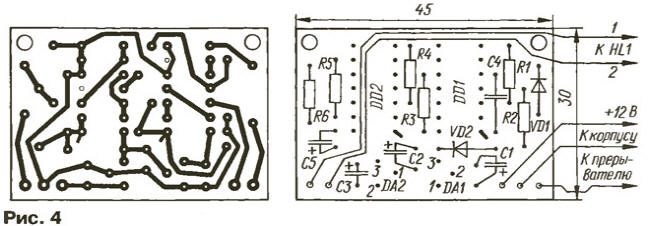
All the details of the indicator, except HL1 led, mounted on a printed circuit Board from foiled fiberglass 1.5 mm thick. a Drawing card is presented in Fig. 4.
If the values of resistors R3-R5 is chosen correctly, usually an indicator of establishing not requires. However, the accuracy of stacking limits of the control zone should be tested. This will require as exemplary suitable angle meter KYC (or described in the first part of this article, or in journal publications [1-3]). The exemplary device and an indicator connected to the breaker serviceable engine and, gradually changing the width of the gap between the breaker contacts either side, mark the limit that will trigger the indicator. If necessary correction, select a resistor R3.
You can verify that the boundary of the zone of control of an indicator using generator 3H, capable of producing rectangular pulses with an amplitude of 9…20 V with adjustable duty cycle.
Ready, the fee should be varnished to protect from moisture and place in the metal shielding box. The led is fixed on the instrument panel in specially drilled hole, and the box with the card placed behind the panel.
Author: I. Potechin, Fokino Bryansk region.