


")

Owners of vintage cars in the operation face a number specific problems and excessive percentage of CO in the exhaust gases, and low responsiveness of the machine, and poor starting performance. Consideration of options to address these issues leads to the conclusion that, in addition engine overhaul or buy a new car, there are more acceptable ways: for example, installation of electronic ignition unit and octane-corrector.
Experiments with electronic components of the ignition, the description of which were published in the magazine "Radio", showed that on the old car the most effective unit proposed by V. Bespalova ("Block electronic ignition". - Radio, 1987, No. 1, pp. 25-27). As for the octane-corrector, none of known did not satisfy me. So I decided to develop their own design with interesting, written by other writers.
It is known that the best performance of a gasoline internal combustion engine can be implemented only when the current ignition timing (OZ) depends on the rotational speed of the crankshaft, from the vacuum in the carburetor, the ambient humidity, the octane number of the fuel used and many other things. On modern high-end models of cars for the purpose establish a very complex and expensive on-Board processors that summarize the testimony of a large number of sensors, taking into account these factors. The creation of such complexes for radio Amateurs difficult.
Your old car is only equipped with a centrifugal Governor OZ and angle vacuum corrector. Fuel, as you know, now trading a few companies, and its quality even with the same stamp can be very different. So experts consider it appropriate manual adjustment of the angle OZ after another refilling.
Described below corrector allows the engine to automatically detain the time of occurrence of sparks at 2.5 MS, with an increase of frequency of rotation crankshaft from 960 min-1 4000 min-1 delay decreases linearly (when 4000 min-1 latency is close to zero). From the driver's cab can be quickly changed the delay range is from 0 to 2.5 MS, which at idle corresponds to the angle OZ 14.4 deg.
Concealer can be used in conjunction with any electronic ignition units. It connect input in parallel with the breaker contacts (see scheme in Fig. 1). The principle of operation is to bypass breaker on the delay time, install the driver.
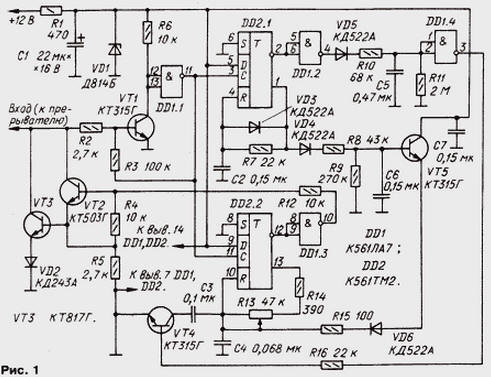
The device is powered by a parametric stabilizer R1VD1. By opening breaker contacts to the base of transistor VT1 closed through the resistor R2 enters the opening voltage. As soon as the transistor VT1 open, high the level at the inputs of the element DD1.1 is replaced by a low, and the output of this element, on the contrary, there is a high level.
At this point run single vibrators collected one on the trigger DD2.1, and the second is on the trigger DD2.2. At the same time a high level, passing through the resistor R3, confirms the on-state of the transistor VT1.
The first single vibrators generates pulses of constant duration. With inverted output trigger pulses after inverting element DD1.2 is input to the Converter frequency-voltage collected on elements VD5, R10, R11, C5, and with direct access on the other such a Converter the elements VD4, R8, R9, C6.
Converter VD5R10R11C5 serves to control the rotational speed of crankshaft shaft in the starting area until the idle speed (i.e. frequency of sparking from 0 to 27 Hz). The principle of operation of the Converter is charging the capacitor of the integrating circuit pulses of constant duration that provides linear dependence of the voltage on the capacitor from the input frequency the pulses.
The second single vibrator with adjustable duration of the output pulses generates the pulse delay sparking relative to the moment of contact opening the breaker. Up to this point, the trigger DD2.2 is in the state 0, the output item DD1.3 applies a low level, therefore, the transistors VT2 and VT3 are closed.
After opening contacts the trigger DD2.2 switches to state 1, in this the currently displayed transistors VT2, VT3, again lowering the voltage on the base transistor VT1 to almost zero. The transistor is closed and the output element DD1.1 again appears low, however, flip-flop States he won't change. The single vibrator generates a pulse delay, the duration of which is determined circuit resistance of resistors R13, R14 and capacitor C4 (if closed the transistor VT4).
The short increase in the voltage at the input of the ignition module, which occurs between the moments of contact opening and opening of transistors VT2, VT3, causes sparks - it will be suppressed "antidopingovoj" input the circuit of the ignition module.
At a frequency of less sparking 27 Hz at the output of the element DD1.4 - high level, the transistor VT4 open, so the capacitor C3 C4 connected in parallel. As a result, the pulse width of the delay increases by 0.5…1.5 MS, easier engine start. At a frequency of 27 Hz (idle speed of the engine and above) at the output of the element DD1.4 level changes from high to low, the transistor VT4 is closed and the capacitor C3 is disconnected from C4 in this case, the delay decreases to the set resistor R13.
The return of the trigger to 0 occurs when you increase the voltage on the capacitor C4 to 4.6 In, after which the capacitor discharges through the resistors R13, R14. The pulse width of the delay generated by the single vibrator on the trigger DD2.2, depends on the initial voltage on the capacitor C4, and his determine the frequency Converter is the voltage on the elements VD4, R8, R9, C6 and the emitter-follower transistor VT5; they do not allow the capacitor to discharge below a certain level.
The greater the engine speed, the higher the voltage at the emitter transistor VT5 and the less time required to charge capacitor C4 to voltage trigger, and hence less delay. At a frequency of sparking 133 Hz (4000 min-1) voltage on the emitter of the transistor VT5 is 4.6 and In the single vibrator on the trigger DD2.2 does not start, delay equal zero. With decreasing frequency the voltage at the emitter VT5 is reduced and the delay recovers.
The rest of the octane-corrector such other, those already known to the readers of the magazine.
All parts except the variable resistor R13, are mounted on a printed circuit Board (Fig. 2) of foiled fiberglass 1.5 mm thick, in which krepjat box, glued a sheet of polystyrene. The Capacitors C50-38 (S1), the rest - K10-7a or K10-17; resistors - MLT. A Zener diode can be replaced DB on TV. Diode VD2 - any of the series CD or CD, the rest of any of the series KD521, KD522, D. Transistors CTG (VT1, VT4, VT5) interchangeable with any of the series KT315 and KT3102 given the Pinout; CTG and CTG - any of the respective series.
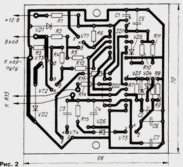
Resistor R13 is set in a convenient location on the dashboard of the car. The handle resistor should be equipped with at least a simple scale with a pointer.
To establish corrector need an electronic oscilloscope with standby mode sweep, electronic frequency counter, power supply at a constant voltage, adjustable in the range 11…14 V and a current of at least 1 amp simulator switch; low frequency square wave pulser.
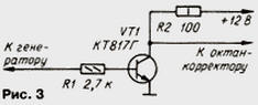
First connect the corrector to the power supply and a voltmeter to measure the voltage the Zener diode VD1 (about 9), which should not change by more than 0.3 V when the input voltage in the range of 11…14 Q. Then to the exit generator connected simplest simulator breaker assembled on the on Fig. 3, mounted on the generator the pulse repetition rate of 25 Hz and control the oscilloscope rectangular pulses with an amplitude of about 12 To the output of the simulator. Connect the output of the simulator to the input breaker octane-corrector and control the oscilloscope passage control pulses the collector of the transistor VT1 and the output element DD1.1.
Choosing the resistor R7, to achieve oscilloscope pulse duration of 3.5 MS the true output of flip-flop DD2.1. Switch the input of the oscilloscope to the output of the element DD1.4, and by changing the oscillator frequency from 20 to 30 Hz, choose a resistor R11, the inverter DD1.4 clearly switched from a single state to zero when crossing the frequency of 27 Hz.
Next, set the input frequency is equal to 133 Hz and pick up resistor R9 to obtain voltage 4.6 V at the emitter of the transistor VT5. Using oscilloscope connected to the direct output of the trigger DD2.2, is satisfied no delay by increasing the frequency of the input signal in excess of 133 Hz.
As the frequency of the input signal from 33 to 133 Hz voltage on the emitter transistor VT5 should change linearly from 0 to 4.6 V. This provide linear delay reduction from the value of the resistor R13, to zero. At the maximum resistance of the resistor R13 is set the greatest delay of 2.4…2.5 MS when the input frequency is 33 Hz selection capacitor C4 and 3,4 3,6…MS when the input frequency is less than 27 Hz selection capacitor C3.
In conclusion, using an oscilloscope pulse sequence control at the input of the corrector. The lower voltage level must be within 0,5…0,7 In, and the top - 11…14 V. Add the length of the lower level can be various - if input frequency less than 27 Hz and the resistance of the resistor R13 maximum, it is equal to 3.5 MS; at a frequency of about 33 Hz resistor R13 her you can change from 2.5 MS to 0, and at 133 Hz and no more delay. If concealer provides the specified parameters, the establishment can be considered finished. Set the concealer in the cabin. Connect concealer to the system electrical equipment, the handle is set to the middle position and run the engine.
After the next refueling clarify the position corrector pen. For this on a flat stretch of highway accelerates the car to direct transmission up to speed about 60 km/h. Sharply tap on the accelerator and appreciate the time during which hear the ringing of the piston pins.
The duration of the ringing with more than 3 illustrates the insufficient delay requiring to reduce the ignition timing corrector pen. In the absence of ringing delay reduced. Optimal consider the duration of the ringing 0,5…1 S.
You can use octane-corrector and a little different. In this case, block the performance of a centrifugal regulator in the interrupter-distributor (or bind rusk wired or disassemble), and the housing of the interrupter - distributor is rotated in the direction of advance of the ignition angle corresponding to the angle 35 OZ grad. relative to the top dead point of the piston of the first cylinder. In this the position change of the angle of OZ will match the factory default settings a centrifugal regulator, i.e. it will be the role of octane-corrector.
Author: A. Sergeev, Kamensk-Shakhtinskiy, Rostov region