


")

This autostorage in comparison with similar devices, published in the magazine "Radio" earlier, does not have any fundamental innovation. However, he interesting that assembled only three chips and four transistors and it has a good set of performance characteristics.
When developing autostorage the author tried to make it as simple as possible and reliable and not containing this expensive and hard to find parts. Another hand, he had to give way to security functions known to the guards his class.
The guard takes the intermittent audible alarm when unauthorized attempt to open the hood or trunk lid of the car. When open the door of the salon this occurs with a certain time delay. The device also reacts to the shock and vibration of the body, for example, when trying removing the wheels or other parts. In this case, the alarm signal will also be somewhat delayed.
In watchman used analog method of forming time intervals. It simplifies the scheme, as it allows to set required values of the segments time without additional hardware costs. Known temperature the instability time exposures inherent in their chosen method of their formation, for krasnosirenevogo device is not very important.
Control the led in the device - two-tone. By the color of its light can to judge which mode of operation is currently in alarm device.
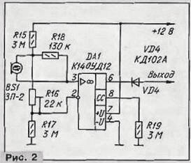
A circuit diagram of the guard shown in Fig. 1. The primary site devices - RS-flip-flop elements DD1.2, DD1:3. Sensors SF1 - SF4 are door switches for interior lighting of the car, SF5. SF6 breakers lighting the trunk and engine compartment, although, apart from them, can be installed and included in the additional parallel switches. Description of the vibration sensor and his work is detailed in [1]. The basis of the sensor is a piezoelectric element from the sound projector CP-2. The signal from the piezoelectric element is supplied to the amplifier-shaper, performed by operational amplifier DА1 (Fig. 2). Sensitivity set trimming resistor R16. If the vibration sensor and shock is not needed, the piezoelectric element and the amplifier-shaper exclude.
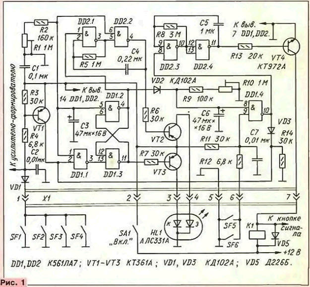
When the device is switched off, all capacitors are discharged. After switching it on tumbler SА1 capacitor C3 through resistors R1, R2 begins to charge. In during this time the output elements DD1.2, DD2.2 is a high voltage level, and the output element DD1.3 - low.
At the same time through the diode \/D2 quickly charging the capacitor C6. Transistor VTЗ opened, and led НL1 shines in red, indicating that goes extract time the device goes into standby mode. During this time, the driver must to leave the cabin and close the door, Other doors, hood and trunk also must be closed.
The shutter speed establish a trimming resistor R1.
To guard moved to the standby mode, the capacitor C3 should be charged to the switching threshold of the elements DD1.1, DD1.2, DD2.2. At this point runs generator, assembled on the elements of DD2.1,DD2.2. pulses low level begins to periodically open the transistor VT2 and permanent red the LEDs НL1 added green blinking with a frequency of 1…2 Hz. The simultaneous illumination of the red and green LEDs emits a color resembling the orange. In standby mode, the device can be arbitrarily long.
Transistor VT1 of the main unit (see Fig. 1) operates in the switching mode. When the closure of the contacts of any of the switches SF1-SF4 transistor VT1 is open the lower circuit on the input of the DD1.1 there is a voltage high-level the trigger DD1.2, DD1.3 is switched and the output element DD1.2 occurs the low voltage level. The capacitor C6 through resistors R9, R10 begin be discharged to the threshold switching element DD1.4. This time (it is installed R10), it is necessary to remove the object from protection without the inclusion of the signal alarm to open the door of the cabin and off the power toggle switch SА1.
After switching on the output element DD1.4 low level changes to high, allowing the operation of the generator on the elements DD23, DD2.4. The pulse generator, operating at a frequency of 0.8 Hz, periodically open power transistor VT4, which relay signals K1 car works with the same frequency.
Doors opening to the color information of the led will change from intermittent red-orange to green immediately, i.e. before an alarm will sound alarm. This will remind the driver that before the end of the time delay necessary disable the guard tumbler SА1.
If you close the switch contacts SF5, SF6, a low level is received in the lower under the scheme the input element DD1,4, at the outlet of the low level element the voltage will be changed to high and allow the generator to the elements DD2.3, DD2.4, as in the above case, only now the alarm will sound immediately.
The differential voltage output of the element DD1.4 through the diode VD3 is held at the bottom by the schema of the input element DD1.1. The trigger switch and lock attempt penetration in the trunk or under the hood of the car. Transistor VТ2 will be opened, and VТ3 - closed, light color NO LEDs will be green.
If enough single led (red glow), should ALSO replace ALL, and a chain R7VТЗ - delete.
When specified on the diagram the values of the transition to the standby mode can be changed within 5…18 C, and the delay time of the signal is 5…10 seconds.
The alarm sounds until the guard is off toggle switch SА1. It conveniently, when the car owner is always around, i.e. within the audible signal of the vehicle. Otherwise, the device will have to Supplement any timer and node locking circuits of the ignition, which of course same complicate the watchman.
Almost all parts of autostorage mounted on the PCB of unilateral foiled fiberglass 1.5 mm thick. a Drawing card is presented in Fig. 3. Board with parts mounted in the casing from the relay-voltage regulator R-B1; good and any suitable durable plastic box. Resistors R1 and R10 placed on the front wall of the box.
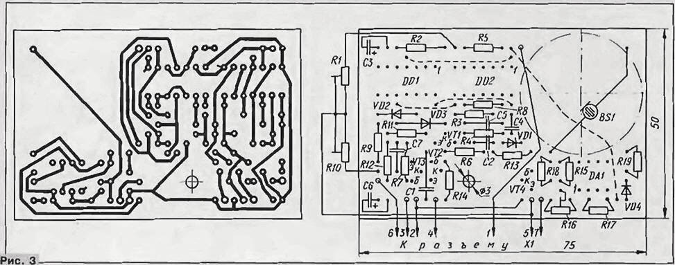
(click to enlarge)
In the device used fixed resistors MLT and capacitors km. Oxide capacitors C3 and C6 must be chosen with low leakage current type K52-1, K50-35. Trimming resistors R1, R10 - JS4-1. Transistors can KTA replace CTB. CTG and CTA - CTB or CT with any letter index. Chip CLA can be replaced by CLA, LA. Instead of the piezoelectric element PZ-2 PZ-5.
Led НL1 installed in the vehicle so that its glow was well visible from the outside, and the device itself is not accessible to the attacker . Where is mounted the toggle switch SA 1, should be known only to the driver.
Connect the device to the on-Board network according to the diagram in Fig. 1 flexible conductors through semicontact connector X1. On those models of cars where the relay sound signals is missing, it must be installed. The resistance of the winding relays shall not be less than 240m. Parallel to the relay coil necessarily include diode D226 (VD5) with any letter index, cathode to the positive power supply conductor.
The device does not require the establishment and with proper detail and correctly performed the installation begins to work immediately. It is only necessary to set the desired the delay of the transition to the standby mode resistor R1, and then the resistor R10 is the delay of the signal.
Literature
Author: W. Pramuka, Togliatti