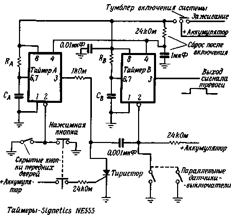
On the basis of just two cheap integrated type 555 timers, you can collect affordable automobile anti-theft system. Its schematic diagram is shown in figure 1.

Fig.1
The timer And performs a dual function - provides exposure time (it is approximately equal to 1.1 RAСA), sufficient not only for the driver, including anti-theft system, managed to get out of the car, but also to ensure that he, sitting in the car, managed to shut down the system. Due to this, the exposure time may be necessary to set out the interior of the car switch, which is always uncomfortable, not to mention the fact that the attacker can always detect this switch. In this case, the toggle switch to turn on and off the system can be hidden somewhere behind the dashboard of the car.
When the system is turned off, the decay of the output pulse of timer L starts the timer When the system is turned on, the thyristor allows you to start the timer In only as from actuation of one of the sensors - switches grounding type located at vulnerable points on the machine.
As a result, the periods of charge and discharge are the same and depend only on R and RR. Therefore, the operating frequency of the circuit, we can write the equation

or

Akim way, the change in frequency depending on temperature is consistent with the change in the voltage in the resistor divider consisting of a thermistor and a resistor divider of this type are often used in a bridge circuit, in order to obtain the linearized voltage dependence on temperature). The output voltage of the divider can be expressed in the form

As in equations (3) and (2) the denominators are the same, the dependence of frequency on temperature in the Converter circuit will have the same appearance and the same degree of nonlinearity, as the dependence of the voltage and temperature for a conventional voltage divider consisting of a thermistor and a resistor.
If you are using a thermistor having at 25° C resistance Ro=5 kω and providing in the temperature interval
from 0 to 50° C resistance change in 9,06 time, the Converter circuit provides at temperatures up to 25° C error due to the nonlinearity of ±0.5° C. This error is reflected in the graph of dependence of frequency on temperature is shown in the figure.
The fact that the value of the frequency in Hertz throughout the operating temperature range coincides well with the value of temperature in degrees Fahrenheit (range 3-46° C corresponds to the interval 37-115° F), is purely coincidental. In the General case the frequency will be linearly dependent on temperature in any interval, but the frequency will be different from the value of temperature.
To minimize the error of the Converter may have to use a highly stable polycarbonate capacitors. In the circuit shown in the figure, were used capacitors with a nominal tolerance of ±5%, and to get the exact value of the frequency for a given temperature, connected parallel to them specially selected capacitors of small capacity.
IC timer itself contributes to the reference frequency depending on the temperature only a negligibly small error. If you do not provide proper isolation of a circuit, the circuit can be somewhat sensitive to changes in the supply voltage.
Author: M. L. Harvey; Publication: N. Bolshakov, rf.atnn.ru


