


")

One of the most successful designs metastorage, I think you should to recognize the device M. Coralsea [1]. It has become a model for subsequent developments by other authors (for example, Bannikova V. [2]).
Although in [1] and [2] to play alarm used dynamic head of direct radiation, in many cases it turns out more convenient to use on the machine beep. Given limited capacity motorcycle batteries, to improve the efficiency of the guard, but not to the detriment of the reliability of the protection, it is necessary to exclude false positives. The issue in the mentioned works focus on, in my opinion, not enough.
It is known that clearly separate the signals of the sensor caused by human factor (not to mention whether with malice), other, arising from exposure to drive-by traffic, wind, etc, not possible. It is therefore desirable to avoid a reaction from the watchman short pulse sensor (at least shorter than 1 s), and especially from single pulses. In other words, the output of the amplifier signals of the vibration sensor directly to the trigger input of a security device it should be recognized disadvantage.
With that said above, the design [1] has been processed. Music synthesizer and amplifier audio frequency replaced by a conventional horn relay. Measures have been taken to reduce the likelihood of false positives. Parasitic acoustic and mechanical feedback between the sensor and audible alarm excluded Berelain method - at the time of alarm electronic Assembly blocking the passage of pulses of the vibration sensor to the input of the guard, and then with some time before the lock is released. Provides contact sensors, increasing the overall reliability of the protection
Schematic diagram of the guard shown in Fig. 1.
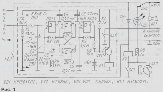
The electronic unit is assembled only on a single chip, but nevertheless contains all the necessary for such devices functional elements: trigger, timer, generator.
The role of the trigger and timer plays the single vibrator, made on the Schmitt trigger DD1.2 and DD1.3. Chain C3R4 determines the pulse width of a high level on the output of single-shot, which corresponds to the length of the tone signal alarm (if indicated in the diagram the values of approximately 23…25).
The Schmitt trigger DD1.4 and castorocauda chain C6R5 assembled the generator frequency about 0.7 Hz. This frequency is periodically switched signal relays K1 - load the current amplifier transistor VT1.
Schmitt trigger DD1.1 provides the insensitivity of the guard to the pulse sensor at the time of the sounding of the alarm and after it was finished on time, determined by the circuit R3C2. This prevents re-triggering under guard the influence of the damped oscillations of the frame of the motorcycle and the piezoelectric element sensor caused acoustomechanical the influence of the audio signal.
Chain R1R2C1 agree on the vibration sensor with electronic site caretaker. This sensor, developed Y. Vinogradov [3], except M. Coralsea and V. Bannikov, too, without changes applied and W. Pramuka [4] in his autostorage. The sensor is good because not only workable in almost any situation, but also easy to the manufacture and cheap.
However, I had to conduct a series of experiments with a Converter mechanical vibrations into electrical (with the piezoelectric element BQ 1 and its mounting details) to increase sensitivity and reliability while working as a guard at the motorcycles. To eliminate false positives Y. Vinogradov proposed to use the analyzer to the pulse counter. With my proposed the Converter works best simplest integrated circuit R2C1 with shunt resistor R1. It takes into account not only remove the frequency of the pulses, but their the duration and amplitude.
Since the capacitor C1 is charged through the resistor R2, and is discharged through the total resistance of the resistors R1 and R2, the time of charging and discharging unequal. It is easy to see that by changing the ratio of the resistors R1 and R2, it is possible to exclude the influence on the work metastorage not only single, in no way mutually unrelated impulses, but also packs (and even continuous oscillations).
This is a very useful feature, for example, to protect against fluctuations caused heavy rain (with appropriate sensitivity of the detector). As noted, if significant vibration intensity at the output of the sensor installed square wave with more or less certain frequency, duty cycle, close to two, and an amplitude equal to the supply voltage. The circuit determines R1R2C1 the delay of the alarm, it is advisable to choose at least 1 s.
Chain R1R2C1 suitable for use with other vibration sensors. Need only matching the values of its parts Motostore triggered when the voltage across the capacitor C1 exceeds the upper threshold switch the Schmitt trigger DD1.1. Application in the watchman of the Schmitt trigger improves shifting precision in a relatively slowly varying the input voltage.
Relay K2 is controlled by the contact sensors SF1, SF2 works in your device additional protection of a motorcycle It can be helpful when you came out of building vibration sensor (or its application is difficult for example to weather conditions) or e-node, and if the motorcycle is beyond visibility (in the woods, in the garage near the house)
The fact that pretty soon the rumor already clearly fixes the background noise of a single enable alarm (you can even count the number of inclusions signal at 17-18 indicated on the diagram the values of the circuit R4C3). This signal clearly indicates the actuation of the vibration sensor, but does not allow us to judge his cause. If resounded signal suddenly interrupted, it should call a legitimate concern. May it be that your motorcycle struck another the vehicle. Then contact sensors turn off the alarm until you intervenes.
As contact sensors (there may be several in parallel) suitable push-button switches and enclosed reed switches. In the diagram presents both options. In the armed mode, the closed contacts of switch SF1 and the reed switch SF2 must be opened, the relay K2 is thus de-energized and its contacts also open.
Button SF1 may be, for example, is installed under the saddle (where usually are tools) so that fixed the latch on the saddle pressed the button and rasmiya contacts. When I try to remove contacts will close.
The reed switch can be installed inside the frame tube, which rotates on bearings the axle of the front wheel fork (this option, however, requires disassembly of the steering node with the dismantling of the upper bearing). The reed switch is attached via a non-magnetic spacer to the inner wall of the tube frame, and the shaft of the plug opposite the reed switch using the same gasket set magnet so that the actuation (opening) the reed switch occurred when turning the steering wheel from one extreme positions about a quarter of the full angle of rotation. In this scenario, when you try to steal a motorcycle, remove the wheel, etc., will be a short circuit of the reed switch.
To facilitate the owner of the installation of the steering wheel to the desired position, is led HL1 After activation of the device, the alarm sounds regardless of the future status of the reed switch, and the led in the protection mode de-energized.
The device is not critical to the selection of parts. Temperature operating environment motorcycle permits the use of capacitors in the timing circuits (used imported miniature ELNA). Relay K1 is compact imported HG4123/012-1C, which allowed to mount it on the Board. Instead it will fit widespread automotive relay, but will have to install a relay near with the signal. Relay K2 is any compact with the corresponding voltage actuation (for example, RAS, passport RS4.569.421-02).
Button SF1 must withstand high mechanical loads - suitable automotive switches, interior lighting, installed on the doors, or the switch from the CU (push button breaker). The reed switch is used with changeover contacts (unused conclusion free to leave).
Charge with the details of the electronic Assembly is placed in a sturdy metal box screen.
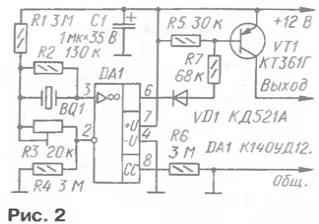
The sensor consists of a transducer of vibration, which is based on a piezo from the sound projector CP-18, and the amplifier-shaper collected at the OS DA1 and transistor VT1 (see scheme in Fig. 2, borrowed from [3]).
The piezoelectric element on a brass plate removed from the housing of the sound projector and soldered thereto two racks of steel elastic wire diameter 0,5…0,7 mm, as shown in Fig. 3. One rack is brazed to the plate edge, and the other to the conductive coating of the piezoelectric element is also close to its edge. Propane stand must remain parallel to one another.
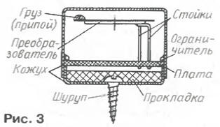
To avoid damage to the piezoelectric element when soldering, it is desirable to use possible more fusible solder and thus reducing the temperature of the heat soldering rod. You should not strive for minimal area of contact solder the piezoelectric element is in the operation of soldering can exfoliate. The optimal size about 3x4 mm Distance between columns of 9.5. 10 mm.
Far from the end stands the resulting console on the edge of a brass plate with the side opposite to the piezoelectric element, napaimiut additional load of solder Adding or subtracting the mass of the load is easy to adjust the sensitivity the Converter.
The free ends of the uprights Converter obluzhivayut and soldered to the Board when final Assembly of the sensor. Cost produce from foil fiberglass thickness of 1.5 mm. Drawing card is presented in Fig. 4. Cost placed in the casing-screen, welded from sheet metal, which is self-tapping screw is attached to the body of the motorcycle. Converter BQ 1 should not at work to touch the walls the casing.
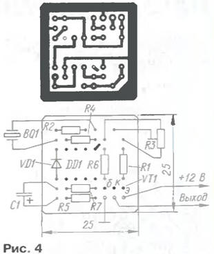
The dimensions of the sensor - 25x25x18 mm It is connected to node e three conductors in secure isolation.
The capacitor C1 in the sensor-K53-19 - locking in the food chain. Fee designed for the installation of the transistor CTG, however, the best results were obtained with import transistor 2SA881R with the same Pinout. Trimmer resistor R2 - SDR-19a.
When establishing a watchman specify your desired time of exposure the selection of the values of RC-circuits. Adjustment of the circuit parameters R1R2C1 is convenient to perform directly on the motorcycle. For this purpose, the resistor R2 is replaced trimmer, instead of the resistor R1 solder the other, resistance 1 …2 kOhm (to limit the collector current transistor sensor), as shown in Fig. 5.
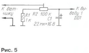
The engine of the resistor is set to the extreme left under the scheme the position - minimum the sensitivity. Then try to remove from the bike any easily removable detail (at least the tube of the gas tank). The trigger guard should not happen. Moving in stages, the engine of the resistor to the right under the scheme, seeking to withdrawal details have clear trigger guard. Manipulation when removing parts should be the same. After each impact sensor must be able to withstand some pause for discharging capacitor C1.
After finding the desired position of the slider of the resistor R2, measure the resistance the resulting shoulders divider and replace their regular resistors.
Before the guard installation in the standby mode, set the wheel of the motorcycle in the position at which the HL1 led will turn off and turn on the power toggle switch SA1.
In conclusion, it should be noted that the reliability of the protection depends largely on secrecy and unavailable (in a reasonable time interval) of its elements and ensuring. Therefore, it is desirable for the battery to provide sturdy metal well lockable drawer beep to protect the casing, and appropriate wiring to put in the frame of the motorcycle. Practical implementation these measures may be different depending on the type of vehicle.
Literature
Author: A. Martemyanov, Seversk, Tomsk region.