


")

The device is designed to automatically turn on a single electronic of the device when turning the other. The first one is called the slave, and the second - leading. A device of similar purpose have been published by the author in the Radio magazine over three years ago (see "Radio", 1996, № 8, p. 51). It the disadvantage was that the key was used electromagnetic relay. The new option is easier, the function keys are triacs. It imposes certain restrictions on the types of the devices used, but this will be discussed below.
Schematic diagram of the device dependent to enable devices with a capacity of 100 watts and more is shown in Fig. 1. Triac VS1 is connected to the socket to connect XS1 the slave device. The host connects to the socket XS2. When it is in off state, the current through the device is not flowing, the triac is closed and the slave the device is de-energized. When you enable the master device through the diodes VD1-VD5 begins leaking current and emerging the voltage (through resistor R1) is supplied to the control electrode of the triac. When a positive half-wave of the mains voltage the current flowing through the master fixture, will pass through the diodes VD1, VD2, and to the control electrode of the triac will receive a positive voltage, which is it and open.
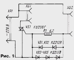
When a negative half-wave of the mains voltage the current will flow through the diodes VD3-VD5 and to the control electrode of the triac will receive a negative voltage. In this case it will be opening. Diodes VD1-VD5 and the resistor R1 limits the amount of current through the control electrode of the triac. Since applied for here triac magnitude of positive and negative control voltages different, the number of series connected diodes to the positive and negative half-wave current varies. The current through the presenter device, wherein the triac is opened, is 50…100 mA, so the slave network device the voltage does not appear at the beginning of halftime, and with some temporarily delay.
The amount of delay depends on the power lead of the device. The presence of delays decreases the tension on the slave device is approximately 7…10, and sometimes and more percent. In addition, since the holding current of the triac normally exceeds 100 mA minimum output slave devices described with reference to the device should not be less than 100 watts. The greatest power of the first fixture is determined by the maximum allowable current through the diodes VD1-VD5 and can reach 1 kW, and the slave - 250 watts. If these diodes and a triac to install the heat sinks, these power will increase accordingly up to 2…3 kW and 1.1 kW.
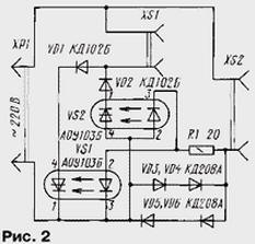
Low-power slave devices (50 W or less) you can use device, scheme of which is shown in Fig. 2. It incorporates two thyristor optocoupler VS1, VS2, which in turn opens each of its wave the mains voltage. They are managed by the current flowing through the master fixture. This current in turn flows through the light emitting diodes of the optocouplers and opens the photothyristors. Diodes VD3-VD6 and the resistor R1 limits the current through the emitting diodes. The maximum power of the master device is determined by the type of diodes VD3-VD6 and in this case is 400 watts. It can be easily increased by the use of more powerful diodes, such as in the device shown in Fig. 1.
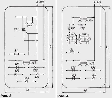
The device, schematic diagram of which is shown in Fig. 1, assembled on PCB from one-sided foil fiberglass (Fig. 3). On it contains all the details, including socket XS1, XS2. The printed circuit Board the device shown in Fig. 2, is shown in Fig. 4. These boards can to perform the functions of the front panel, but in this case all details must be closed by a casing made of insulating material.
In the device (see Fig. 1) you can use any silicon rectifier diodes with a current capacity consumed by a leading instrument. In the device (see Fig. 2) applicable diodes KD105B, DB (VD1, VD2) and similar. Diodes VD3-VD6 you should also choose based on the maximum current consumed by the world's leading device.
So on the slave device was a normal voltage, the thyristors in the device due to open at the beginning of each half cycle of the mains voltage. It means that the master device should consume current during the entire halftime the mains voltage. These devices can be heating (without thyristor power regulators) or lighting (incandescent and also without regulators). If will be leading the electronic devices powered by rectifier and the consuming current is near the maximum voltage, then the led devices mains voltage will be supplied at the beginning and around the middle each half-wave of the mains voltage. In the case where the functions of the slave perform heating or lighting appliances, they work in low power. If the slave will be the electronic device, for example, block supply with step-down transformer and rectifier, which consumes the current the maximum voltage, it will work fine.
Establishing device (see Fig. 1) is reduced to the selection of the minimum number series connected diodes VD1-VD5 at which the triac steadily included at the beginning of each half cycle of the mains voltage. The voltage these diodes should not exceed 6 V. Similarly and configure the device (see Fig. 2), thus it is necessary to choose the number of series connected diodes VD3-VD6.
Author: I. Nechaev, Kursk