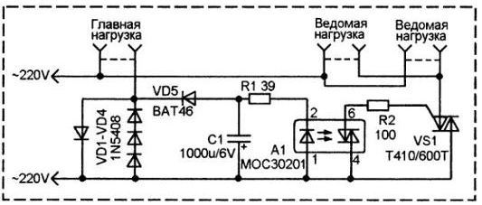
In some cases, the dependent must enable devices powered by outlet. Simple circuit shown in the figure allows you to control two slave loads depending on the inclusion of the main load.

Actually, the slave loads may be more, - they are all included parallel to each other.
The power to the main load comes from the power supply 220 through the chain of diodes VD1-VD4. Each of these diode drops about 0.7...0.8 In direct voltage.
When the load is switched on at the mains voltage passes to the main load through these diodes, and series-connected diodes VD2-VD4 drops around the 2.1...2.5 V. the Diode VD1 is to skip the other half and in the formation of this voltage does not participate.
The negative half is allocated diode VD5 and fed to the capacitor C1, which accumulates a DC voltage sufficient to nominal the illumination of the led of the optocoupler. A1. Open triac optocoupler, followed power triac VS1 Includes the driven load. The 1N5408 diodes can be replaced diodes CD for a voltage below 400 V rectifier Or other similar power and voltage. The number of series connected diodes in the circuit VD2-VD4 you may need to specify when creating a may be used instead of three, and four diodes. It is important that the voltage on C1 is sufficient to enable slave loads via optocoupler A1.
Author: B. We Can Say


