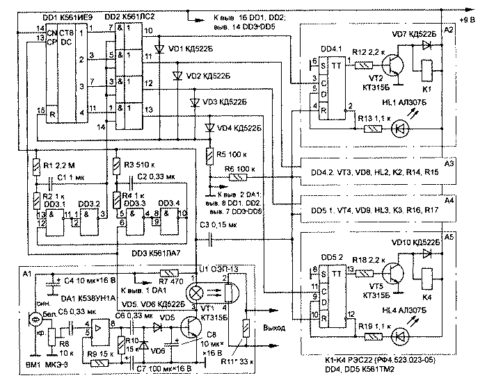
The machine described in the article, besides its basic function - on-off four loads by the number of claps in hands, can manage any device lighting effects. It the use will also help to construct a dynamic load.
In most devices lighting effects apply the master oscillator, the frequency of which is variable resistor. The speed of switching of lamps or lights when this does not coincide with the tempo of the music, and you have to manually reconfigure the generator under each tune. The proposed acoustic machine (see diagram) allows you to switch garlands in accordance with the tempo of the music. When no sound lamp switch with the minimum frequency set by resistor selection R11.
Acoustic machine in the original version controls the lighting effects device (see "help the radio Amateur", 1990., No. 108); the relay of the fourth channel is used for its inclusion. The sensitivity of the machine is adjustable trimpot resistor R8 so that he reacted to the music, but was not changing channels load switching. Practice shows that in addition to involved the fourth channel can be used second or third, but from the first generally to give up, because when you increase the volume it is possible trigger.

With microphone FM signal is input to amplifier-limiter, made on the chip COA. After amplification the signal is detected by diodes VD5, VD6 and is supplied to the base of transistor VT1. In its collector circuit resistor optocoupler U1, which controls the generator device lighting effects. With increasing sound volume opens the transistor VT1, the output impedance of the coupler is reduced, which leads to the increase of the switching speed of garlands.
When accented cotton transistor Vt1 opens completely, waiting multivibrator is triggered on elements DD3.3, DD3.4, which generates a low level pulse duration of about 0.1 s (determined by the resistance of the resistor R3 and the capacitance of the capacitor C2). On the edge of this pulse starts the second standby multivibrator elements DD3.1, DD3.2, which also generates a low level pulse duration about 1.5 C. during this time (determined by the resistance resistor R1 and capacitor C1) DD1 chip counts the pulses, corresponding to the number of claps. For example, there were four. Output 4 the counter-decoder DD1, set the high voltage level.
After a four-second pulse at the control input of the chip DD2 (pin 14) low logic level replaced high. At the outlet of the fourth (top scheme) logical element chips DD2 will also set the high voltage level. It is fed to the input R of the counter-decoder DD1, zeroing it, and at the same time toggles the trigger DD5.2. The opened transistor VT5 controls electromagnetic relay K4, through his contacts (not shown) connect the appropriate load. The HL4 led signals the inclusion the fourth channel of the machine.
The differentiating circuit sets all C3R6 triggers in the initial state when power on the machine.
Block A1 can be used separately only for device management lighting effects. If this is not necessary, instead of the optocoupler U1 in the collector circuit of the transistor VT1 include a resistor resistance of 10 ohms.
Publication: N. Bolshakov, rf.atnn.ru


