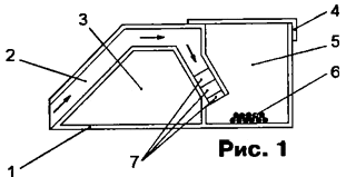
The proposed trap for crawling insects, sketch designs which depicted in Fig. 1, initially, was not "electrified". Her body 1 (approximate dimensions 140x45 mm) glued dichloroethane sheet organic glass or other plastic with a smooth surface. Attracted the smell lures 6 insects (composition bait should be chosen most attractive to them) move on the input channel 2 a height of 10...15 mm the direction of the arrows, and fall into the compartment 5, covered with a lid 4. To get back on a smooth vertical walls of the compartment they can't.

Practice has shown that many insects, well restrain on the surface a declining portion of the input channel, and avoid the sad fate, and if you make this site is vertical, it is not included in this report. An improved trap the nearest bait the end of its input channels were established with small - less than a millimeter - gap three electrode 7 of aluminum foil glued to the surface of the channel. Extreme electrodes connected together, connected to one, and the average - to the other pole of the high voltage pulse generator.
Now an insect crossing the gap between the electrodes, is exposed to electric pulse temporarily loses consciousness and falls into the Bay 5. The presence of two gaps increases the probability of this event. Generator pulses, shown assembled in Fig. 2 the scheme, together with battery power housed in the compartment 3 traps.

(click to enlarge)
The elements DD1.1 and DD1.2 form a multivibrator generating symmetric rectangular pulses with a frequency of approximately 4 Hz. Differentiated chain C5R5, impulses trigger a single-shot on the elements DD1.3 and DD1.4. Each the output pulse of the single vibrator 5ms opens the transistors VT1 and VT2. At the moment closing the VT2 transistor in the circuit L1C7 oscillations, and the amplitude the first (positive) half-cycle exceeds 100 V. It is safe for person, but enough to stun the insect. Opened in the second (negative) half cycle, the diode VD1 shunt circuit, stopping the oscillations.

(click to enlarge)
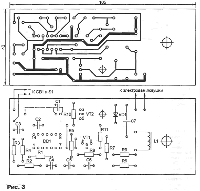
The printed circuit Board of the generator (Fig. 3) unilaterally made of foil PCB thickness 1.5 mm. All resistors - MLT-0,125, condenser S1 - oxide K50-35, K50-29 (the latter set, as shown in Fig. 3 bar line) or their imported counterparts. Capacitor C7 - C-2, others - K10-17B or other ceramic. Armour the magnetic circuit of the coil L1 is formed by two cups 430 ferrite MMM-16. Its winding has 1500 turns of PEV-1 to 0.14. Battery GB1 - "Crown", the switch S1 of any type. The device consumes current not more than 1 mA.
Author: A. Boutsko, Tomsk


