


")

When hard to see, the person is taken for the binoculars. But if I can't hear? As to make became well heard of, say, birds singing in the distance?
In such cases helps device, which not only multiplies the faint sounds, but also improves the signal - to-noise. This device, let's call it "the acoustic telescope", should be quite portable.
A circuit diagram of a receiver and amplifier sound weak signals shown in Fig. 1.
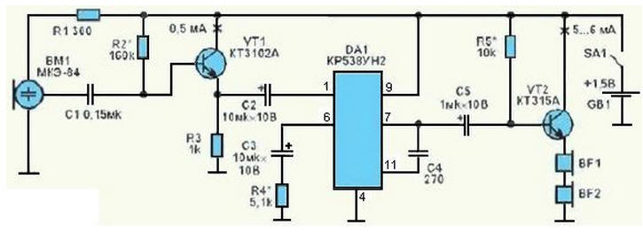
Fig. 1
At the entrance it is sensitive electret microphone WM, the signal amplification provides chip DА1, which has a very high gain voltage with a low noise floor. To reconcile relatively low input resistance of this amplifier with high input impedance microphone entered a matching stage transistor VT1 included in the scheme emitter follower. To listen used miniature, put in the ears phones. They (BF1, BF2) is connected to the amplifier on the transistor VT2, the output impedance matching circuit and the resistance headphones. The power source device is one of a galvanic item GB1 with a voltage of 1.5 V, which consumes a current of about 6…7 mA. In the role of a horn, the bottom of which is placed the microphone may be cylindrical or conical tubes with a diameter of 5…6 cm and a length of about 30 cm For convenience and the best safety in the "camp" conditions pipe make foldable, telescopic, using some sliding of glasses from the road plastic with long bottoms.
In Fig. 2 shows another self-made design that consists of three dvigausciesya one into the other sections, glued together out of cardboard. Internal section your end is attached to a plastic box-the body where you installed the the BM1 microphone. Inside the case are the details of the amplifier, the source and a power switch. Here it is expedient to provide a place for storage phones that are in working position are removed and linked to your amplifier regular cord. If you're not listening to birds, and lecturer, the device can to put, say, on the table, the input sound channel in the right direction, but the hands are free to write the summary.
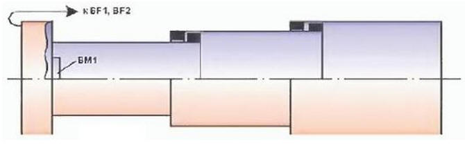
Fig. 2
Accessories take miniature - type resistors MLT-0,125, capacitors C1 - K10-17, C4 - KLS, the rest K53-1. For sound reproduction use stereodinamikami the resistance of the voice coil of the order of 20 Ohms. The power source will serve as a miniature, but large enough for our purpose galvanic element R03 AAA batteries.
The selection of the values of resistors R2, R5 can be customized collector currents transistors to values indicated in the diagram of figure 1. It is also useful to change the resistance of the resistor R4 (in the range 0…10 kOhm), achieving best sound in the phones. Selection of the nominal value of R4 is simplified if its the choice to temporarily include a variable resistor to 10 ohms, connecting the output of the slider one extreme conclusions. Found experimentally the amount of resistance can measure with an ohmmeter or estimate the angle of rotation of the axis, if the "resistor" is taken from linear response (type a) changes in the resistance. The figure to the right shows the pin used for the chip relative to tags-"the key".
Author: P. Yuryev