


")

The proposed device is intended for automatic control vibrionaceae "Baby", "Brook" and the like for operation in boreholes (wells) low water flow or for periodic pumping of groundwater. In the machine applied non-contact water level sensors installed directly on lifting the hose, allowing it to be used in wells of small diameter.
Vibronics (Fig. 1) with a water hose hanging on a metal wire well. On the hose installed sensors top water level (VU) and lower level (WELL). The device is based on the change in conductivity between the common electrode, which is used as a metal cable suspension pump and the electrodes of the sensors in the water and outside it.
Fig. 1. Placement of vibronics in the well: 1 - water in the well, 2 - vibrance, 3 - the lower level sensor, 4 - sensor top level 5 - water hose, 6, 7 - lead wires of the sensors, 8 - rope suspension pump - common electrode.
The condition of the sensors analyze the logical node on the chip DD1 (Fig. 2).
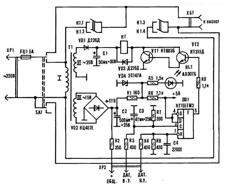
Fig. 2. Schematic diagram of automatic XP2 device
The cycle of operation of the machine proceeds as follows. When the sensors of the upper and the lower levels are in the water, the conductivity between the wire and the electrodes of both sensors is large, and when the power toggle switch SA1 at the inputs R and C trigger set logic 1, resulting in the same level its direct output, causing the opening of a key on transistors VT1, VT2, and the actuation of the relay K1, which contacts K1.3, K1.4 connects the pump to the network.
When pumping water, the pump will turn off only when the input R DD1 will logic 0, i.e. when the water drops below the lower level sensor. It the trigger condition is characterized by a logical zero value on its direct the output that causes the closing of the transistor switch, deactivating the relay and pump.
After pump shutdown, the water level in the well begins to rise, and when she reaches the lower level sensor, the input R of the trigger appears set to 1, that, however, does not turn on the pump, because at the input is present voltage logical zero, and up to the upper level sensor water hasn't risen. And only after the water rises in the well to the upper level sensor at the entrance With DD1 appears voltage logic 1, and on its direct output is also set logical 1; turns on transistor switch, relay and pump: the process of pumping water repeats.
Resistors R2, R3, R4, R8 are used to set the required logical values on the trigger inputs.
To prevent shorting between the rope and rings, first isolated by three layers of PVC tape on a plot of length of 30-40 mm. Wires are led out to the connector plug, mate which is installed on the box; there are outlet plug the pump. Wire and cable presentazioni to lift the hose.
When installing the device in the well with a metal casing should so hang the pump to completely eliminate the touch sensors to the pipe.
When installing without error to establish the device will be required. For sustainable work at the inputs R and the trigger should be the voltage of 3-5 V (the sensors are located in the water). Depending on the resistance layer of water between the sensors and cable the specified voltage is selected via the resistor R2. The current through the sensors are not exceed 5-10 mA with a resistance layer of water between the sensors and cable 1.5 to 2 ohms.
Fig. 3. Printed circuit Board arrangement of elements
Fig. 4. The location of the sensors on the hose: 1 - the lower level sensor, 2, 6, 7 - lead about water, 3 - lift hose, 4 - rope suspension pump, 5 - upper level sensor, 8 - PVC tape
Assembled device check at home (on the table), having made for this purpose, the layout of the sensor and using suitable container of water and instead pump plug a table lamp.
Authors: L. Romanov, V. Kireev