


")

We offer our readers a machine supports comfortable in the kitchen temperature, turning on and off the fan. However, this is not the thermal stabilizer in the usual sense of the word. The principle is based on several different principle…
The starting point for the creation of the machine was the fact that when working the stove the hot air is distributed through the room is far from equitable. Heat rises, and coming from outside remains cold at the bottom. So, the difference in the readings are installed near the floor and the ceiling of the room thermometers reaches 8°C even during operation of the appliance at a quarter power. Average air temperature depending on the season and time of day were in the range of 16…32°C.
The boundary between layers of air are expressed quite sharply and clearly felt by man. In this situation the presence of beneficial in the kitchen fan stirring the air. With its incorporation of the temperature at the bottom rises and upstairs - reduced. Such a fan is desirable to provide a timer automatically after some time breaking it. It will protect from the consequences of forgetfulness. Even better - make a device that reacts to the uneven distribution of temperature and comprising the fan, only when it is really necessary.
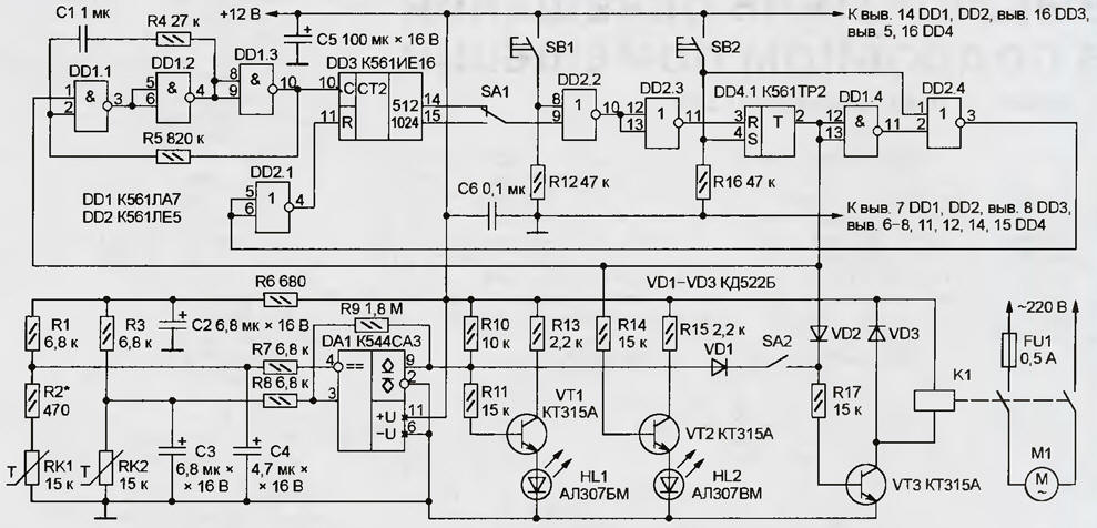
In the machine which is schematically shown in the figure, combined both functions. Main nodes timer - RS-trigger DD4.1, a clock generator on the chip DD1 and binary counter DD3. In the initial state of the timer, which is set clicking the button SB1, the output of the trigger DD4.1 (pin 2) and connected to him the input 1 of the element DD1.1 is a logic low. As a result, the work the clock generator on the elements DD1.1 and DD1.2 prohibited. A high level on the input R of the counter DD3 in all its bits set to log. 0. The transistors VT2 and VT3 is closed (assuming the switch SA2 is open), the led is not HL2 off, the fan motor M1 is disconnected from the network normally open relay contacts K1.
(click to enlarge)
By pressing the SB2 turns on the fan and start the timer. As a result status change trigger DD4.1 voltage logic high with him output goes to the base circuits of transistors VT2 and VT3. Led HL2 ignited and triggered the relay K1 network delivers the voltage to the fan. At the same time allowed the operation of the clock generator DD1.1, DD1.2 and counter DD3. After a certain, dependent on the position of the switch SA1, the number the oscillation periods of the clock generator, a logic low at the input 9 element DD2.2 will be changed to high, which will lead to the return of the trigger DD4.1 and only timer to its original state and turn off the fan.
A fan even before the expiry of the exposure can be disabled with the button SB1 and again enable button SB2, and the countdown will start from the beginning. Extend the work fan and a simple press on the button SB2.
Sensor temperature difference is assembled on the comparator DA1. His sensitive elements - two thermistor. The first of them (RK1) is placed at a height of 2.2 m and no more than 0.8 m from the cooker horizontally. Second thermistor (RK2) under the first set at a height of approximately 0.6 m.
If the temperature of the thermistors, equal, and their resistance. However, due to the resistor R2, the voltage at inverting input (pin 4) of comparator DA1 higher than the noninverting (pin 3), the result at its output (pin 9) - low logic level. Transistor VT1 is closed, HL1 led is extinguished. The fan, if it is not included with the button SA2, it's not working.
For example, the temperature of both of the thermistors increases or decreases in the same way. With her change, remaining equal, their resistance. Therefore, the state of the comparator remains unchanged. However, if the thermistor RK1 heating is stronger than RK2, the voltage at inverting input comparator DA1 will be lower than the noninverting that will switch of the comparator. Voltage logic high with his exit will be opened the transistor VT1, and if the switch SA2 is closed, and VT3. Led HL1 lights up, the relay K1 is triggered, the fan is on regardless of the state of timer. After equalization of the temperature of the thermistor comparator DA1 will return to its original state by turning off the fan.
Capacitors C2 - C4 are used for noise suppression and interference on a long wire, connecting the thermistors with the device. The value of capacitor C4 intentionally selected smaller than C3. This allowed to eliminate momentary power switch fan at the time of filing on the machine voltage.
Voltage of 12 V to power the machine you take from any stable source. Current consumption (not counting relays K1) does not exceed 30 mA. The author of applied relay ATC-1 (passport RA). Suitable and other, for example, RAS (passport RF4.523.023-05.01).
The device can be mounted fixed resistors of any type. The Capacitor C1 Is film series K73, C6 - ceramic, the remaining oxide K50-6 or K50-35. LEDs HL1 and HL2 - any of the corresponding color of light, for example, KIPDA (red) and IPDB (green). You can replace both with one dichroic General the cathode, for example, L-117EOW Kingbright company. Transistors VT1 - VT3 - with any letter index.
The comparator CSS replace SS into consideration the differences in the numbering of conclusions. When no chips KTR RS-trigger (DD4.1) collect well-known scheme of two elements of the chip CLE or other OR-NOT. Lowering the supply voltage to 9, instead of the chipset series C you can install their functional counterparts from C.
The resistors RK1 and RK2 - MMT-4. Its value (resistance at temperature +25 °C) is not critical and can reach 82 ohms, however, the thermistors should be same, best of all - "one box". If there is doubt about the identity characteristics of thermistors, the equality of their resistance it is useful to check if different temperature. When installed in the machine, the findings of the thermistors, United with their metal hulls, connect to GND.
Turn the power machine, Razumkov switch SA2 and pressing SB1 "start", you must make sure that the clock on the elements DD1.1, DD1.2 operates, the led HL2 is lit, and the relay K1 is worked by running the fan. In otherwise you'll have to check the correctness of installation, serviceability chips, transistors and other elements. If the switch SA1 is shown in the diagram position after 15…20 minutes the fan should be automatically turned off and the led HL2 is out. The switch SA1 to another the position will double that time. To set the duration of fan operation with high accuracy in this case is not required, but if necessary, it can "customized" selection of the values of capacitor C1 and resistor R5.
Verify that the timer, proceed to the establishment of the sensor the temperature drop. The resistors RK1 and RK2 in advance are placed in such a way that they warmed to the same temperature. In this state make sure that the logic level at the output 9 of the comparator DA1 - low, and HL1 led is not lit. If you heat the thermistor RK1 several degrees, close to it is a hot subject matter, the led should light up, and after some time after removal of the object from going out. The required sensitivity of the sensor achieve the selection of the resistor R2.
Be aware that during the soldering of the elements of the machine are heated to high temperature, altering their characteristics. Therefore, after each interference in a device with a soldering iron you should wait a few minutes giving the elements to cool down.
In conclusion empirically choose the best location resistors RK1 and RK2.
Author: N. Lutchenko, Moscow