In the magazine "Radio" has been variously described different designs for automatic pump control, water tower, for instance devices, tracking water level or in the source or receiving tank, or in both places. Sometimes it is more convenient to run the pump manually, and the machine to place the the function of monitoring the overflow tank. In a published article author offers two simple options for this machine.
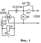
The circuit of the machine is quite simple, if you use a float switch water level sensor (Fig. 1). With incomplete receiving tank sensor contacts SA1 open. After clicking the button SB1 mains voltage is supplied to the electric motor pump M1 and through the capacitor C1 and the rectifier bridge VD1 to the coil electromagnetic relay K1. The relay is activated and its contacts K1.1 blocks button contacts SB1.

When filling a receiving tank to a predetermined level, the contacts SA1 sensor closed, relay K1 releases, its contacts when it opens and off the motor M1 from the network. The device enters the initial state. For starting the pump must again press the button SB1.
The ballast and capacitor C1 serves to reduce the voltage across the relay coil to its working value, the resistor R1 limits the current to recharge the capacitor in the time of contact closure sensor SA1.
In the machine used in the relay RPU-2 with a winding resistance of 4.5 ohms and work with a voltage of 110 V. It has a special coil over the part of the magnetic that makes the relay insensitive to voltage ripple power. When using another relay to provide the operating voltage at its the coil may have to enable parallel output diagonal of the bridge VD1 a capacitor has a capacitance of about 1 μf, for a voltage not less than 160 In and pick up the capacitance of the capacitor C1.
Button SB 1 must be rated for full current of the pump motor, and the capacitor C1 is to have a working voltage of At least 400 (e.g., K73-16 or K73-17). Bridge VD1 - any for a voltage of less than 300, you can apply four a separate diode at the same voltage.
However, the float sensor is not very convenient. The contacts are connected to the network wires that require increased safety measures during operation.
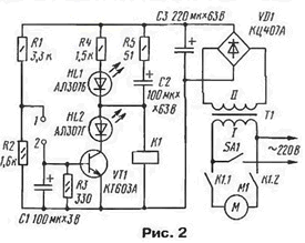
In Fig. 2 is a diagram of the machine with a proximity sensor, electrodes which are connected to the inputs 1 and 2. The power supply voltage is supplied to the device when the closure of the contacts of the switch SA1. If the receiving tank is not filled fully, the base current of the transistor VT1 is zero and it is closed. Voltage 27 To 30 from the output of the rectifier through a chain R5C2 is supplied to the coil of relay K1, which triggered at the moment of inclusion SA1 and their contacts K1.1 and K1.2 includes the pump motor. As the charging of the capacitor C2, the current through the relay coil K1 decreases, but to hold enough current flowing through the resistor R4. HL1 led red glow lit and indicates the inclusion of machine.

When filling the tank there is a current between the electrodes of the sensor and the transistor VT1 opens. Its collector current lights the led HL2 green glow indicating the filling of the tank, and turns off the relay K1. Contacts To 1.1 and K1.2 the relay opens and the pump motor stops. Spending in the water the base current of the transistor VT1 becomes zero, it will close the led HL2 will go out. The relay, however, will not work, because of the current flowing through resistor R4, is not enough. For starting the pump must be turned off and re-enable SA1.
Capacitor C1 suppresses crosstalk on the wires going to the sensor electrodes, resistor R5 limits the current to recharge capacitor C2. the current through transistor VT1 at the time of its inclusion. The voltage divider R1R2 sets the voltage on the electrodes of the sensor and limits the base current of the transistor VT1.
The device is assembled by the method of surface mounting in the housing of the industrial photoelectric RFS. From it were used relays, power transformer, circuit Board and the contact pad. Relay - MCM-48. PA4 passport.501.088 the resistance of the winding 510 Ohm operating voltage of 24 V. Transformer must provide on the secondary winding voltage 22...26 V with a load current of at least 50 mA. You can use any transformer series TN with four secondary windings, connected in series, as well as many transformers at CCI appropriate connection of their secondary windings, for example, TPP. TPP. TPP - TPP. At independent manufacture of the transformer can use the tips in the magazine "Radio" 1997 g. № 7. p. 36, 37, the Resistors will fit any, oxide capacitors - any working the voltage of C2 and C3 is not less than 40 V. it is desirable to use LEDs the specified color of the glow. Bridge VD1 must be rated for a voltage of less 50 In, be possible to apply four separate diode at the same voltage. Transistor VT1 average power structure of the n-p-n, for example, series KT. CT, CT. CT with any alphabetic indices, as well as high power - series KT815. CT. The switch SA1 is calculated on the total current of the pump motor. The author used conventional electrical wall switch, setting it outside the case the device in the gap of the phase conductor of the network.
The use of a relay with two pairs of contact closure eliminates the appearance of voltage on the wires stretching across the garden plot, the idle pump. If the relay has only one pair of contacts, they should be put in the gap of the phase conductor of the network. Also possible replacement of the switch SA1 button carried by the relay contacts (see Fig. 1) after filling the reservoir of the device is de-energized. In this embodiment of the machine the led HL2 is not needed.
The receiving tank is a plastic barrel with a volume of 200 L. It installed in the attic of the garden house. The electrodes are two segments galvanized steel pipe, introduced into the barrel from the top of its threaded tube. On one tube, reaching to the bottom of the barrel, are filling and selection of water in running water in their homes. The other (its length is about 80 mm. and connected to it plastic corrugated pipe) is used to drain excess water when the barrels overflow due to mechanical failure or breakage of the wires leading to the sensor.
Author: P. Aleshin, Moscow


