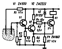
A schematic diagram of a simple machine comprising feeding water to a controlled area of the soil (such as in a greenhouse) while reducing its moisture content below a certain level, shown in the figure. The device consists of an emitter follower transistor V1 and the Schmitt trigger (with transistors V2 and V4). Actuator control solenoid and relay K1. Moisture sensors are two metal or carbon electrodes. submerged in the soil.

When sufficiently moist soil resistance between the electrodes is small and therefore, the transistor V2 is opened, the transistor V4 is closed and the relay K1 is de-energized.
As the drying of the soil resistance of the soil between the electrodes increases, the bias voltage on the basis of transistors V1 and V3 decreases, Finally, at a certain voltage on the base of the transistor V1 is opened, the transistor V4 and relay K1. The contacts (not illustrated) short circuit incorporating the damper or electrical pump carrying water for watering the controlled area of the soil. When humidity increases, the resistance of the soil between the electrodes decreases, after reaching the required level opens the transistor V2, the transistor V4 is closed and the relay is de-energized. The watering stops. The variable resistor R2 sets the triggering threshold of the device, making ultimately depends on soil humidity in the controlled area. Protection of the transistor V4 from the surge voltage of negative polarity when switched off, the relay K1 is performed by the diode V3.
Note. The device can be applied to the transistors CTG (V1, V2), CTA (V4) and diodes D226 (V3).
Literature
Publication: N. Bolshakov, rf.atnn.ru


