


")

Circuit diagram:
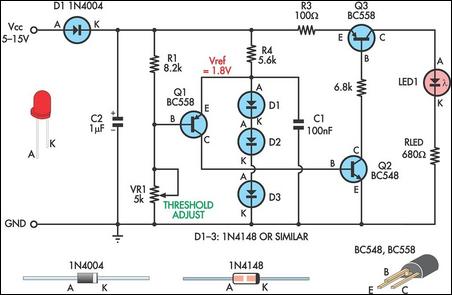
Low Supply Rail Detection Circuit Diagram
This turns on Q3 in proportion to this bias current which then drives LED1. The brightness of the LED gives an indication of the severity of the low voltage condition. The brighter the LED, the lower the supply voltage. Trimpot VR1 is adjusted so that LED1 just comes on at the desired low-voltage point. The current consumption is typically less than 2mA when LED1 is off. Finally, the value shown for RLED is suitable for 6-12V operation. For other voltages, RLED can be calculated using the formula RLED = (Vcc - 1.8)/0.01 (this equates to a current of about 10mA).
Author: Trent Jackson