


")

During testing, adjustment and repair of various electronic equipment there is often a need to quickly check the presence of voltage and determine its polarity at different points of the device, wires, power connectors, etc. For these purposes, especially during the work in "field" conditions, it is convenient use a simple small-probes-indicators. In Fig. 1 shows the scheme is simple probe voltage and polarity to a two-color led HL1. Input voltage indicator - 3,5… 18 V, current consumption in this case is from about 1 to 15 mA. In accordance with the flowing current is changed the brightness of led.
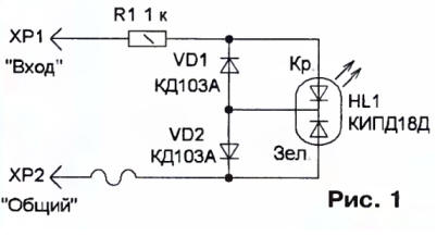
Resistor R1 limits the current through the led and diodes VD1 and VD2 are included, so depending on the polarity of the controlled voltage light one crystal led. When the input voltage of the positive polarity current flows through current limiting resistor R1, crystal red glow and the diode VD2, and therefore the illumination of the led will be red. When changing polarity it will turn green. If the input AC voltage, light color yellow.
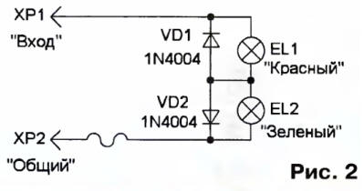
In some cases, it is necessary not only to check the voltage and polarity different power sources, e.g. batteries batteries or galvanic elements, but also to assess their condition and load capacity. For this it is convenient use a probe, which includes a load consuming a certain current. As you can use the load of an incandescent lamp. The scheme of such a probe is shown in Fig. 2. With its help determine the polarity controlled voltage, the lamp EL1 should be heat resistant paint varnish or close to the red color filter, and EL2 - green. Working voltage probe and power determine the current applied to the lamp filament. For a compact probe suitable miniature lamp series SMM.
To check the various nodes SW radio receivers range in which there is high frequency voltage, it is possible to apply the probe to a circuit it is shown in Fig. 3. He works in the frequency range 1 …30 MHz and displays the voltage from 1.5 to 20 V. Input (HR) connected to a controlled circuit, and Shoop XP2 - to GND. The capacitor C1 is ballast and limits the input high-frequency current, the diodes VD1, VD2 rectify the AC voltage, the resistor R1 is additionally limits the current through the led HL1.
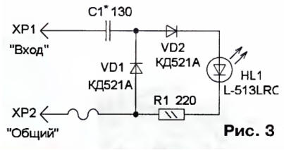
The selection of the capacitor C1 can change the sensitivity of the probe. The increase the capacitance of this capacitor along with increased sensitivity leads to ascending shunt effect on controlled circuits due to reduced the input impedance of the device. When working with the probe, it is recommended first be connected to the circuit input only HR without attaching the probe 2 to GND. If the led is not lit, plug and dipstick XP2.
The basis of all probes can be the case of a pen with an internal diameter of less than 7 mm. it placed most of the elements, connect them with segments installation of wire, and the rations were isolated using PVC tubes. As the probe CHR you can use the pin from the connector or a sewing needle. To connect indicator to a common wire of the device is a flexible stranded wire length 10…20 cm at the end of which you can install an alligator clip.
The probes used resistors MLT, S2-23, the condenser km-5, CT, K10-17, diodes KDA interchangeable with any low-power rectifier, CDA - diodes KDA, KDB. Led lights in a plastic casing with a diameter of 3 5 mm… increased brightness.
Author: V. Efremov, G. Essentuki, Stavropol territory