


")

The principle of operation
The metal detector is a relatively simple device, electronic scheme which provides good sensitivity and stable performance.
A distinctive feature of this device is its low operating frequency. The inductance coil of the metal detector operate at a frequency of 3 kHz. It provides:
- on the one hand, weak reaction to unwanted signals (e.g., signals, resulting from the wet sand, small pieces of metal, etc.);
- on the other hand, good sensitivity when searching for hidden water pipes and runs the Central heating, coins and other metal objects.
Generator detector excites oscillations in the transmitting coil frequency at 3 kHz, creating in her an alternating magnetic field. Receiving coil is perpendicular to a transmitting coil so what passes through the magnetic lines of force will create a small EMF. The output receiver coil signal is absent or very small.
Metallic object entering the field of the coil changes the inductance. At the output of an electric signal which is then amplified, rectified and filtered. Thus, the output system includes a DC voltage signal, the value which slightly increases when approaching the coil to a metal object.
This signal is supplied to one of inputs of the comparator circuit, which compares with the reference voltage, which is applied to its second input. Level the reference voltage is adjusted in such a way that even a slight increase voltage signal changes the state of the output of the comparator circuit. This, in turn, actuates electronic switch. As a result this process weekend amplifying cascades receives the audio signal, informing the operator about the presence of a metal object.
Schematic diagram
Schematic diagram of the detector is presented in Fig. 2.38.
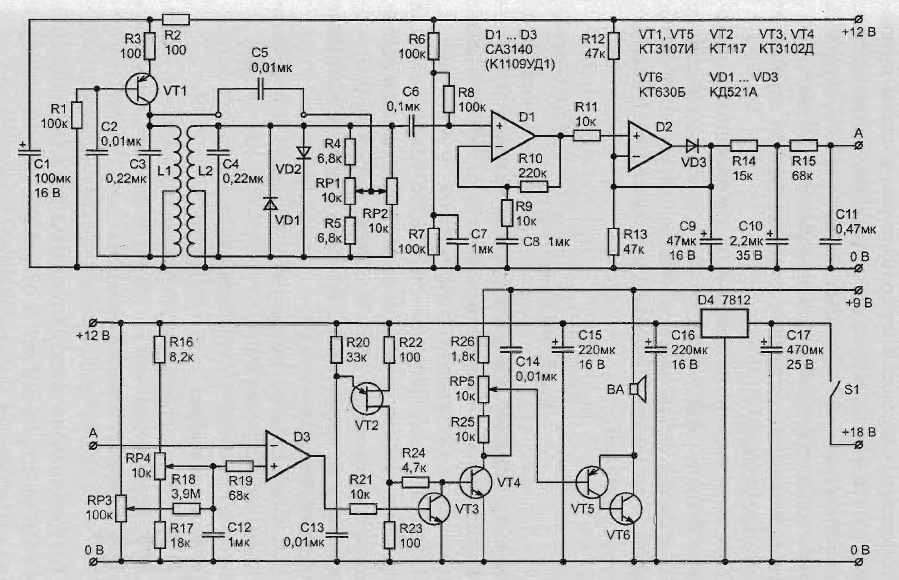
Fig. 2.38. A schematic diagram of an electronic detector with a low operating frequency (click to enlarge)
The transmitter, consisting of transistor VT1 and related items, excites fluctuations in the coil L1. The signals to the coil L2, and then amplified chip D1 and straightened chip D2 connected in the circuit of amplitude detector. The signal from the detector is supplied to the capacitor C9 and is smoothed by the filter low of frequencies, which consists of resistors R14, R15 and capacitors XU and C11.
Then the signal goes to the input of the comparator circuit D3, which compares with a reference tension mounted variable resistors RP3 and RP4. Generator, assembled on the transistor with one shift VT2, works in the continuous mode. However, the signal generated by them is fed to the base transistor VT4 only when the is closed the transistor VT3. After all, being in the open state, the transistor shunt generator output.
Upon receipt of the signal at the input of the circuit D3, the voltage at its output decreases, closes the transistor VT3, and the signal from the transistor VT2 through the transistor VT4 and volume control RP5 is supplied to the output stage and the speakerphone.
Power supply schematic
The circuit uses two power supplies, which eliminates the possibility the occurrence of any feedback the output of the circuit sensitive to its input. The main circuit is powered by a battery voltage of 18 V, and chip D4 is reduced to a stable voltage of 12 V. the decrease the battery voltage during the operation of the circuit does not change the settings device.
Output stages are powered from a separate power source voltage of 9 V.
Requirements for power consumption is quite low, so the power supply device you can use three batteries. Battery power output stage does not require any special switch, as in no signal output stage consumes almost no current.
Installation diagram
A diagram of the detector it is recommended to mount it on the breadboard. Such Board depicted in Fig. 2.39. The Board has 24 copper strips 50 holes in each with a step of 2.5 mm. First of all, in strips need to do 64 of the cut and to drill three installation hole.
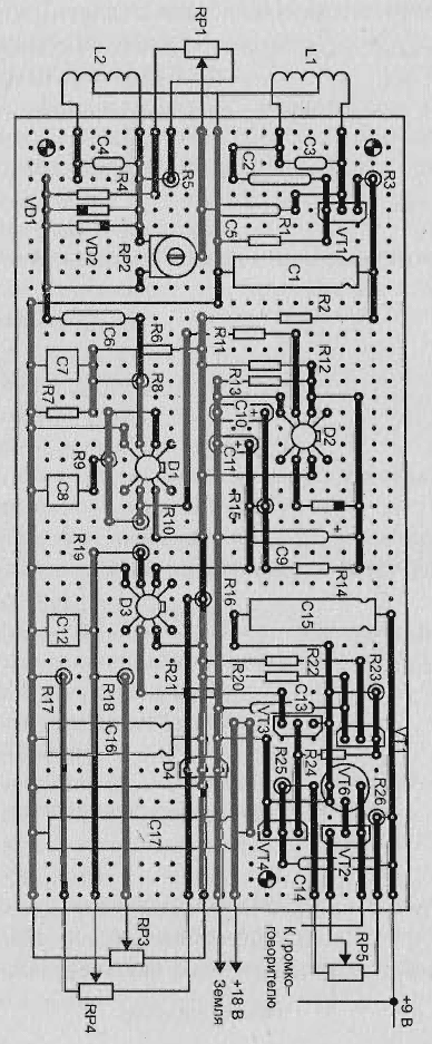
Fig. 2.39. The printed circuit Board and the arrangement of the elements
Then on the reverse side of the Board you need to install:
- 20 jumpers;
- pins for external connections;
- two-pin for capacitor C5.
You can then install the capacitors C16, C17 and chip D4. These elements form a power source with a voltage of 12 V. Check this cascade is accomplished by temporarily connecting the battery voltage of 18 V. the voltage across capacitor C16 should be 12±0.5 V.
You can then move on to assembling the elements of the output stage:
- resistors R23-R26;
- capacitors C14 and C15;
- transistors VT4-VT6.
The body of the transistor VT6 is connected with its collector, so body contact with adjacent elements and lintels invalid. As the output stage in the absence of a signal does not consume current, it helps to check the temporary connection of loudspeaker, AC resistor RP5 and battery voltage of 9 V.
Then you need to install resistors R20-R22 and the transistor VT2, form generator audible signals. When connecting two power supplies in the dynamics bugged background sound changing with the position of the volume knob. After that on the Board it is necessary to mount the resistors R16-R19, capacitor C12, VT3 transistor and an integrated circuit D3.
Checking the operation of the comparison circuit
The operation of the comparator circuit is verified as follows. To the measuring input D3 you need to connect the variable resistors RP3 and RP4. This input is generated by a two resistors of 10 ohms, one of which is connected to positive power bus +12V and the other to the zero bus. The second terminals of the resistors connected to pin 2 IC D3. The jumper is from this conclusion serves as a temporary connection point.
When coarse tuning (on both batteries), which is variable resistor RP4, in a certain situation is the disruption of the audio signal, while the fine adjustment variable resistor RP3 should be a smooth change of the signal close to the situation.
Preliminary checking of the cascades
When these conditions are met, you can proceed to install the resistors R6-R15, capacitors C6-C11, diode VD3 and circuits D1 and D2. After turning on the power source, first you need to check the signal at the output chip D1 (pin 6). It should not exceed half the value of the source power (approximately 6 In).
The voltage on the capacitor C9 should not differ from the output voltage the signal of this chip, although interference from AC power can cause a small increase of the voltage. Touch your finger to the input of the circuit (the base of the capacitor C6) causes an increase in voltage due to the increase of noise level.
If the controls are in the position in which the audio signal no, a finger of the capacitor C6 leads to the appearance and disappearance of the audio signal. At this preliminary checking of the cascade ends.
Final check and adjustment
Final check and adjustment of the detector are performed after manufacturing inductors. After preliminary testing stages of the scheme on the Board you can set the remaining elements, with the exception of the capacitor C5. Variable resistor RP2 temporarily set to the middle position. Cost be attached to L-shaped aluminum chassis with a plastic washer (for eliminate the possibility of a short circuit) with the three screws.
The chassis is secured in the housing of the remote control two bolts that hold the two clip, designed for mounting in the console case to the boom of the seeker. Side of the chassis secures the power source in the housing. When assembling the panel should ensure that the findings of a switch on the reverse side of the variable resistor RP5 do not touch Board elements.
After drilling rectangular holes to glue the speaker. Rod and the connecting portion forming a head mount finder can be made of plastic tubes with a diameter of 19 mm. The head of the seeker is a plate diameter of 25 cm, made of durable plastic. The inner part should be thoroughly cleaned sandpaper, which provides good bonding with epoxy.
The manufacture of the transmitting coil
The main characteristics of the detector is largely dependent on the applied coils, therefore, their manufacture requires special treatment. Coils having the same shape and size, you should wind up on the D-shaped the loop that is created from pins mounted on a suitable piece of Board.
Each coil shall consist of 180 turns of enameled copper wire 0,27 mm with a branch from the 90 turns.
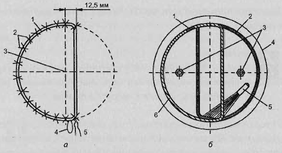
Fig. 2.40. The coil of the metal detector: a method of winding coils; b - scheme of the installation the finished coils
Before you remove the coil from the pins, in their several places need to be tied up, as it is shown in Fig. 2.40, and. Then each coil must wrap the sturdy thread that coils tightly to each other. The manufacture of the transmitting coil ends.
The receive coil manufacturer
Receive coil must be fitted with screens. The shielding coil is provided as follows. First you need to wrap the wire, and then wrap a layer of aluminum foil, which again need to wrap the wire.
This dual coil ensures good contact with the aluminum foil. In the windings of the wire and the foil should be a small gap or clearance, as shown in Fig. 2.40, 6, preventing the formation of a closed loop on the circumference of the coil.
The Assembly of the metal detector
Constructed of coils must be secured with clips around the edges plastic plates and connected to the control unit using a four-wire shielded cable.
Two Central drainage screen and receive coil connected to the zero bus through these wires.
Health check
If you turn on the detector and the radio receiver that is close to coil, you can hear a high-pitched whistle (frequency detector), due to the fire alarm sound in the radio. This indicates the serviceability of the generator of the detector.
In this case, no matter which band is configured with a radio, so check instead, you can use any cassette player.
Place the operating position of the coils is determined by:
- either the output signal of the detector, which should be minimal;
- or search for indications of the instrument (voltmeter) connected directly to the capacitor C9.
The second option is to fit the coils much easier.
The voltage on the capacitor should be approximately 6 V. After that the external parts of the coils can be glued with epoxy resin, and the inner, through the center, should be left loose, allowing the final configuration.
Final configuration
Final configuration is to install loose parts in coils a situation in which the items of nonferrous metal, such as coins, cause a rapid increase of the output signal, and the remaining objects a slight decrease. If the desired result is not achieved, it is necessary to swap the ends of one from the coils.
It should be remembered that the final setting or adjustment of the coils needs be carried out in the absence of metal objects. After you install and durable fastening of the coil should be covered with a layer of epoxy the resin and then apply fiberglass to epoxy seal resin.
After fabrication of the head seeker should undertake the following steps:
- in a scheme to embed the capacitor C5;
- variable resistor RP1 is set to the middle position;
- variable resistor RP2 to set the minimum output signal.
Thus on one side of the middle position of the variable resistor RP1 provides recognition of steel items, and on the other side of colored objects metal. At each change of the nominal value of the resistance of the variable resistor RP1 need to be completely re-configuring the device.
In practice, the detector is a light, well-balanced, sensitive device. For the first few minutes after start the device can be imbalance is zero, but after a while he disappears or becomes insignificant.
Publication: www.loktek.ru