


")

The metal detector is a relatively simple device, an electronic circuit which provides good sensitivity and stability. A distinctive feature of such devices is its low operating frequency. The inductance coil of the metal detector work at a frequency of 3 kHz. This ensures, on the one hand, weak reaction to unwanted signals (e.g., signals generated in the presence of wet sand, small pieces of metal, etc.), and on the other hand, a good sensitivity to hidden water pipes and Central tracks heating, coins and other metal objects.
For the implementation and configuration of the scheme requires the appropriate skills and experience.
The block diagram of the detector is shown in Fig. 1.
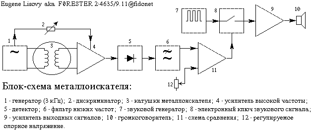
Generator detector excites oscillations in the transmitting coil frequency at 3 kHz, creating in her an alternating magnetic field. Take-up spool is perpendicular to a transmitting coil in such a way that through the magnetic lines of force will create a small EMF. The output receiver coil signal is absent or very small.
Metal the subject, getting into the field of the coil changes the inductance value, and its output is an electrical signal which then is amplified, rectified and filtered. Thus, the output of the system have a signal DC voltage whose value slightly increases when approaching coil a metal object. This signal is supplied to one of inputs of the comparator circuit, which compares with a reference voltage, which is applied to its second input.
The reference voltage level adjusted so that even a small increase in voltage the signal causes the state change at the output of the comparator circuit. It turn actuates electronic switch, as a result something for the weekend amplifying cascades receives the audio signal, informing the operator about the presence of a metal object.
Schematic diagram of the detector is presented on Fig. 2.
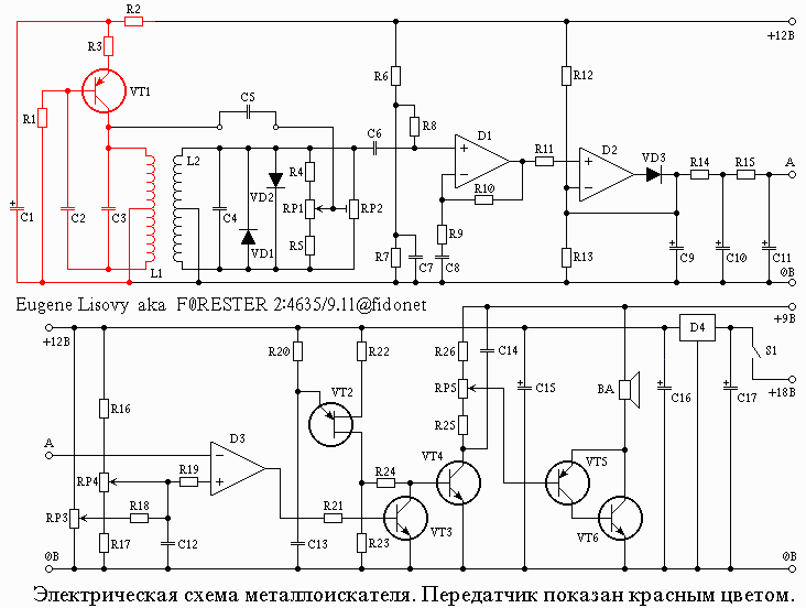
The transmitter, consisting of transistor VT1 and related items, excites oscillations in the coil L1. Signals, coming to the coil L2, and then amplified by chip D1 and straightened chip D2 connected in the circuit of the amplitude detector. The signal from the detector is supplied to the capacitor C9 and is smoothed by the filter low of frequencies, which consists of resistors R14, R15 and capacitors C10 and C11. Then the signal goes to the input of the comparator circuit D3, which compares with reference voltage set variable resistors RP3 and RP4. Variable resistor RP4 is used for quick and rough adjustment, and RP3 provides a precise reference voltage. Generator, assembled transistor with one shift VT2, operates in the continuous mode, however the signal generated by them is fed to the base of transistor VT4 only when closed, the transistor VT3, as being in the open state, this transistor bypasses the output of the generator. Upon receipt of the signal at the input chip D3, the voltage at its output decreases, closes the transistor VT3 and the signal from the transistor through the transistor VT2 VT4 and volume control RP5 is supplied to the output stage and the loudspeaker.
The circuit uses two power supplies, which eliminates the possibility the occurrence of any feedback the output of the circuit sensitive to its input. The main circuit is powered by a battery voltage of 18 V, and chip D4 is reduced to a stable voltage of 12 V. the decrease the battery voltage during the operation of the circuit does not change the settings. Output stages are powered from a separate power source voltage of 9 V. Requirements for power consumption is quite low, so the power supply device you can use three batteries. Battery power the output stage does not require any special switch, as in the absence signal output stage does not consume current.
The metal detector is a complex device, so the Assembly diagram should be parascale with careful check of each cascade. Scheme mounted on a circuit Board, on which there are 24 copper strips 50 holes in each with a step of 2.5 mm. primarily in pinstripes doing 64 slit and drill three pilot holes. Then on the reverse side of the Board set of 20 jumper pins for external connections, as well as two pin for capacitor C5.
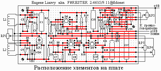
Then install capacitors C16, C17 and chip D4. These elements form the source voltage 12 V. Check this cascade is carried out by temporary connection of a battery voltage of 18 V. the voltage the capacitor C16 must be 12 +- 0.5 V. this is followed by a installation of elements of the output stage: resistors R23-R26, capacitors C14 and C15 and transistors VT4-VT6. Note that the body of the transistor VT6 is connected with its collector, so body contact with adjacent elements and jumpers invalid. Since the output stage when no signal is not consumes current, check the temporary connection of loudspeaker, variable resistor RP5 and battery voltage of 9 V.
Then install the resistors R20-R22 and the transistor VT2, forming the sound signal. When connecting two power sources in dynamics bugged sound background, changing with the position of the 's volume knob. Then on the Board mounted resistors R16-R19, capacitor C12, the transistor VT3 and chip D3. The operation of the circuit the comparison is verified as follows. To the measuring input D3 connect the variable resistors RP3 and RP4. This input is generated by a two resistors of 10 ohms, one of which is connected to positive power bus +12V and the other to the zero bus. The second terminals resistors connected to pin 2 IC D3. Jumper from this pin is a temporary connection point. When coarse tuning (both included battery), which is a variable resistor RP4, in a his position is the breakdown of the audio signal, while at the exact setting variable resistor RP3 must be carried out a smooth change signal near that situation. When these conditions are met, proceed to installation of resistors R6-R15, capacitors C6-C11, diode VD3 and circuits D1 and D2.
After turning on the power source, first check for the signal at the output chip D1 (pin 6). It should not exceed half the value of the source power (approximately 6 In). The voltage on the capacitor C9 should not be different from the voltage output of this chip, although interference from AC can cause a small increase of the voltage. Touch your finger to the input of the circuit (the base of the condenser C6) calls the increase in voltage due to the increase of noise level. If the regulators the settings are in the position in which the audio signal is absent, touch your finger capacitor C6 leads to the appearance and disappearance of this signal. At this preliminary checking of the cascades ends.
Final check and adjustment of the detector is carried out after fabrication of inductors. After a preliminary check of the cascades circuits on the Board are the other elements except capacitor C5. Variable resistor RP2 is temporarily installed in the secondary position. Board mounted to L-shaped aluminum chassis using plastic washers (to eliminate the possibility of a short circuit) with the three screws. The chassis is secured in the housing of the remote control two the bolts holding the two clips for attaching the housing panel to the rod of the seeker. Side of the chassis fixing power supplies in the enclosure. When assembling the console, you should verify that the conclusions of the switch on the rear side of the variable resistor RP5 not touch Board elements. After drilling rectangular holes glued the speaker.
Rod and the connecting part forming a head mount finder made of plastic tubes with a diameter of 19 mm. the head finder represents a plate diameter of 25 cm, made of durable plastic. The inner part is carefully cleaned with emery paper that provides good bonding with epoxy.
The main characteristics of the detector is largely dependent on the applied coils, so their manufacture requires special attention. Coil having the same shape and dimensions wound on a D-shaped contour, which formed from Stipa mounted on a suitable piece of Board (Fig.4).
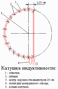
Each coil consists of 180 of turns of enameled copper wire 0.27 mm with a branch from the 90 turns. Before you remove the coil from the pins, in their several places ligated. Then each coil is wrapped with a durable thread that coils tightly adjoined to each other. The manufacture of the transmitting coil ends. Foster the coil should be fitted with screens. The shielding coil is provided as follows. At first she wrapped wire, and then wrapped by a layer of aluminum foil, which is again wrapped with wire. This dual coil ensures good contact with aluminum foil. In the windings of the wire and the foil must be a small gap or clearance, as shown in Fig. 8, prevent the formation of a closed loop around the circumference of the coil.
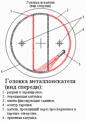
Constructed coils are fixed with clamps on the edges of the plastic plates and are connected to the control unit using four-wire shielded cable. Two Central drain and screen the receive coil are connected to the zero bus through the shielding wire. If you turn on the device and the radio that is close coil, you can hear a high-pitched whistle (frequency detector), due to the fire alarm sound in the radio. This indicates the serviceability of the generator of the detector. In this case, no matter what the range is configured on the radio, so to check instead use any cassette player. Place the operating position of the coils is either determined by the output signal of the detector, which must be minimum, or according to the indications of the measuring device (voltmeter), connected directly to the capacitor C9.
The second option for Ogonki coils much easier. The voltage at the capacitor should be approximately 6 V. the external the parts of the coils are glued with epoxy resin, and the inner passing through the center, remain loose, allowing you to have a final setting.
Final configuration is to install loose parts the coils in such a situation, in which the items of nonferrous metal, for example coins, cause a rapid increase of the output signal, and the remaining items - a slight decrease. If the desired result is not is achieved, you need to swap the ends of one of the coils. Should remember that the final setting or adjustment of the coils needs be carried out in the absence of metal objects. After installation and durable fastening of the coil is covered with a layer of epoxy resin, then on them superimposed fiberglass and all of this is sealed with epoxy resin.
After the manufacture of the seeker head in the schema is embedded capacitor C5, variable resistor RP1 is set to the middle position, and AC the resistor RP2 is set to minimum output. In this case, for one towards the middle position of the variable resistor RP1 provides recognition of steel items, and on the other side of items from non-ferrous metal. It should be borne in mind that with every change the nominal value of resistance of the variable resistor RP1 is necessary re-configuring the device.
In practice, the detector is a light, well balanced, sensitive. during the first few minutes after powering on the device can be imbalance is zero, however, after some time it disappears or becomes insignificant. The elements of the detector ------------------------------------------------------------- Resistors: R1, R6, R7, R8 100 kω R2, R3, R22, R23 100 Ohm R4, R5 6,8 kOhm R9, R11, R21, R25 10kω R10 220 Ohm R14 15 ohms R15, R19 68 ohms R16 8,2 kOhm R17 18 ohms R18 3,9 MOhm R12, R13 47 kOhm R24 4.7 Ohm R20 33 ohms R26 1.8 kOhm Variable resistors: RP1, RP4 10 kOhm (linear) RP2 10 kOhm (microminiature, with horizontal installation) RP3 100 ohms (linear) RP5 10 kOhm (combined with selector) Capacitors: C1 100 µf, 16 V (electrolytic) C2, C5, C14 0.01 UF C3, C4 0,22 µf C6, C13 0.1 UF C7, C8, C12 1 µf C9 47 µf, 16 V C10 2.2 UF capacitor, 35 In C11 0.47 µf, 35 V C15, C16 220 µf, 16 V (electrolytic) C17 470 µf, 25 V (electrolytic) Transistors: VT1, VT5 BC214L (CTB, CTE) VT2 TIS43 unijunction (CT) VT3, VT4 BC184L (CTD) VT6 BFY51 (CTD) Diodes: VD1, VD2, VD3 1N914 (CDA) Chips: D1, D2, D3 CA3140 (COD) F4 mA78L12AWC voltage regulator +12 V, 100 mA (KEN, KEN)
Author: Eugene Lisovyi, Ukraine, Uman; Publication: N. Bolshakov, rf.atnn.ru