


")

We offer to your attention a differential magnetometer can be very useful for searching large iron objects. This device it is impossible to search for treasures, but it is indispensable when you search shallowly sunken tanks, ships and other military equipment.
The principle of operation of the differential magnetometer is very simple. Any item of ferromagnetic distort the natural magnetic field of the Earth. To such subjects is everything made of iron, cast iron and steel. Largely affect the distortion of the magnetic field and magnetization own items, which often occurs. Fixing the tension deviation magnetic fields from background values, we can conclude about the presence of near the measuring device object of ferromagnetic material.
The distortion of Earth's magnetic field away from the target a little, and it is estimated by the difference of signals from two spaced some distance sensors. So the device is called a differential. Each sensor measures the signal proportional to the magnetic field. The greatest distribution got ferromagnetic sensors and sensors based on the precession magneton protons. In this device uses the sensors of the first type.
The basis of ferromagnetic sensor (also called fluxgate) is a coil with a core of ferromagnetic material. Standard curve the magnetization of this material is well known from school course of physics and has taking into account the effect of Earth's magnetic field, shown in Fig. 29.
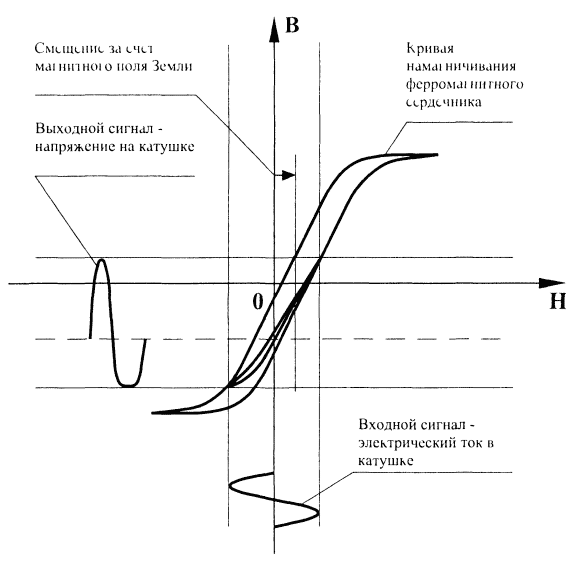
Fig. 29. Magnetization curve.
The coil is excited by a variable sinusoidal carrier signal. As it is seen from Fig. 29, the shift of the magnetization curve of the ferromagnetic core coil by the external magnetic field of the Earth causes the induction field and the associated voltage on the coil start to be distorted unbalanced way. In other words, the voltage sensor when the sinusoidal current carrier frequency will differ from that of the sine wave is more "flattened" tops of half. And these distortions will be asymmetric. In the language of spectral analysis, this means the appearance in the spectrum of the output voltage of the coil even harmonics, the amplitude which is proportional to the magnetic field of the bias field of the Earth). Here these even harmonics and need to "catch".
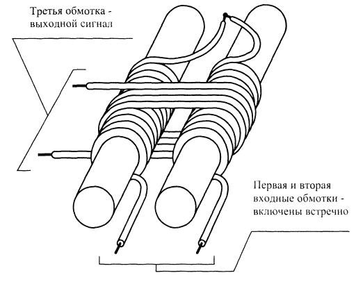
Fig. 30. Differential ferromagnetic sensor
Before you mention naturally suggest themselves for this purpose a synchronous detector operating with a reference signal of twice the carrier frequency, consider the design of the advanced variant of the ferromagnetic sensor. He is of two cores and three coils (Fig. 30). At its core, this the differential sensor. However, for simplicity, hereinafter we will not call its differential, as the magnetometer and the already - differential :).
The structure consists of two identical ferromagnetic cores with identical coils arranged parallel next to each other. In relation to stimulating electrical signal to the reference frequency they are on the counter. The third coil is a winding is wound on top of two stacked together the first two coils with cores. In the absence of external bias magnetic field electrical signals of the first and second windings are symmetrical and in ideal operate so that the output signal of the third winding missing since magnetic fluxes through her fully compensated.
In the presence of external bias magnetic field, the picture is changing. One or the another core at the peak of the corresponding half-wave "flies" in the saturation deeper than usual due to the incremental impact of Earth's magnetic field. In the result of the output of the third winding, you receive the error signal twice frequency. The signals of the basic harmonic ideally, there are fully compensated.
The convenience of the considered sensor is that its coil can enable to increase the sensitivity in the oscillatory circuit. The first and second - in oscillating circuit (or circuit) that is configured on a carrier frequency. Third in an oscillatory circuit tuned to the second harmonic.
The described sensor has a pronounced pattern. It the output signal is maximum at the location of the longitudinal axis of the sensor along the power lines of an external constant magnetic field. When the longitudinal axis is perpendicular power lines - an output signal equal to zero.
The sensor considered, especially in conjunction with the synchronous detector, can to work successfully as an electronic compass. Its output signal after rectification proportional to the projection of the intensity vector of the Earth magnetic field on the axis sensor. Synchronous detection allows you to read and sign this projection. But even without the sign - orienting the sensor low signal, get directions to the West or to the East. Focus to the max - get directions magnetic field lines of the Earth. In the mid-latitudes (e.g. in Moscow) it is inclined and "stuck" in the ground in the direction to the North. The angle of the magnetic declination can roughly estimate the geographic latitude.
Differential ferromagnetic magnetometers have their advantages and disadvantages. The advantages include the simplicity of the device, it is not difficult radio direct amplification. The disadvantages include the complexity manufacturing sensors - but the accuracy required is absolutely exact match the number of turns of the respective windings. An error of one or two turns may to reduce possible sensitivity. Another disadvantage is "compassest" of the device, i.e. the impossibility of full compensation field of the Earth the subtraction of signals from two spaced sensors. In practice, this leads to false signals when turning the sensor around the axis perpendicular to the longitudinal.
Practical design
Practical design of differential ferromagnetic magnetometer was implemented and tested prototype variant without special electronic parts for an audible indication to a microammeter with a zero in the middle scale. The scheme is an audible indication can be taken from the description of the metal detector by the principle of "transmit-receive". The device has the following parameters.
Main technical characteristics
- Voltage - 18 In 15…
- Supply current - 50 mA
Depth of detection:
- gun - 2 m
- gun barrel - 4 m
- the tank is 6 m
Structural scheme
Structural scheme shown in Fig. 31. Stable quartz sets the generator produces a clock is input clock frequency for the signal generator.
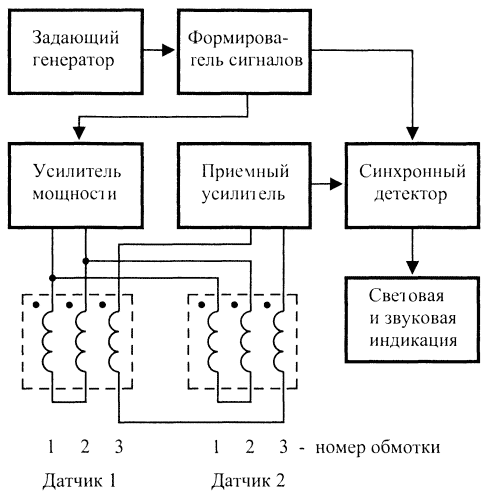
Fig. 31. Structural diagram of differential ferromagnetic magnetometer
On one of its output has the waveform of the first harmonic coming on power amplifier, emitting stimulating coil sensors 1 and 2. Another way forms the meander reference to the doubled clock frequency with a shift of 90° for synchronous detector. The difference signal from the output (third) winding sensors is amplified in the receiving amplifier and rectified by a synchronous detector. The rectified DC signal can be registered by the microammeter or described in previous chapters devices audible indication.
Schematic diagram
A schematic diagram of a differential ferromagnetic magnetometer shown in Fig. 32 - part 1: the master oscillator, the signal generator, power amplifier and emit coil, Fig. 33 - part 2: pick up coils, a receiving amplifier, a synchronous detector, indicator and power supply.
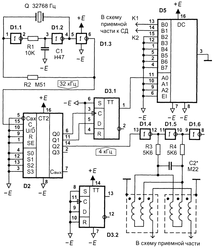
Fig. 32. Schematic - part 1
The master oscillator is assembled on the inverters D1.1-D1.3. The oscillator frequency stable or crystal / ceramic resonator with resonant Q a frequency of 215 Hz = 32 kHz ("quartz clock"). The circuit R1C1 prevents the excitation generator at the highest harmonics. Through the resistor R2 is shorted circuit environment, through the resonator Q - chain PIC. The generator is simple, low quiescent current, reliably operates with supply voltage of 3…15 V, does not contain setup items and too high resistance resistors. The output frequency oscillator - 32 kHz.
The signal generator (Fig. 32)
The signal generator is assembled on a binary counter D2 and D of the flip-flop D3.1. Type binary counter unprincipled, its main task is to divide a clock the frequency by 2, 4 and 8, thus obtaining, meanders with frequencies of 16, 8 and 4 kHz respectively. The carrier frequency for the excitation of the emitting coils-4 kHz. Signals with frequencies of 16 and 8 kHz, acting on D-flip-flop D3.1, is formed at its the output of the square wave is doubled relative to the carrier frequency 8 kHz, shifted by 90° relative to signal output 8 kHz binary counter. This shift required for normal operation of the synchronous detector, as the same shift has a useful error signal twice the frequency at the output of the sensor. Second other chips of two D-flip-flops - D3.2 the scheme is not used, but its unused inputs must be connected either to a logical 1, or to logic 0 for normal operation, as shown in the diagram.
The power amplifier (Fig. 32)
The power amplifier with the mind and therefore does not think and is just powerful the inverters D1.4 and D1.5, which are in antiphase swinging oscillatory circuit, consisting of series-parallel connected radiating coils of the sensor and of the capacitor C2. The asterisk near the nominal capacitor means that it the value specified approximately and that should be selected during commissioning. Unused inverter D1.6, so as to leave the input unconnected, inverts the signal D1.5, but practically works as "idle". Resistors R3 and R4 limit the output current of the inverters to an acceptable level and, together with the oscillating circuit form a high-q bandpass filter, whereby the shape of voltage and current in the emitting coils of the sensor coincides with sinusoidal.
Receiving amplifier (Fig. 33)
The receiving amplifier amplifies the differential signal from the receiving coils sensor, forming a capacitor together NW oscillatory circuit, configured to double the frequency of 8 kHz. Thanks trimpot resistor R5 subtraction of the signals of the receiving coils made with some weighing coefficients that can be changed by moving the slider to the resistor R5. This achieved compensation neodenticula parameters foster the windings of the sensor and minimizing his "compassest".
Receiving the two-stage amplifier. It is assembled at the shelter D4.2 and D6.1 with parallel OS voltage. The capacitor C4 reduces the gain at higher frequencies thus preventing the overload of the high frequency amplification path interference from power networks and other sources. Correction circuit OU - standard.
Synchronous detector (Fig. 33)
Synchronous detector is made at OS D6.2 in the model scheme. As analog keys used the D5 chip CMOS multiplexer-demultiplexers 8 to 1 (Fig. 32). His digital address signal is moved only in the low-order, providing alternate switching points K1 and K2 on a common bus. The rectified signal is filtered capacitor C8 and enhanced OS D6.2 while an additional the weakening of the unfiltered RF components chains R14C11 and R13C9. Chain correction OU - standard used for type.
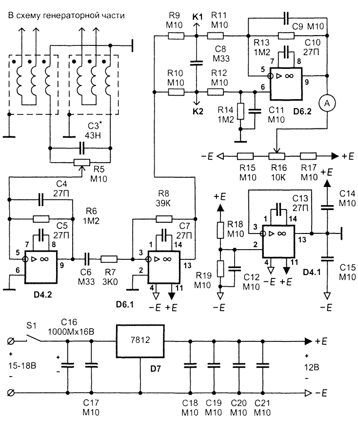
Fig. 33. Schematic - part 2. The receiving amplifier
The indicator (Fig. 33)
Indicator is a microammeter with a zero in the middle of the scale. In flat parts can be used circuitry previously described metal detectors of other types. Including, as an indicator of possible use and design of the metal detector on the principle of electronic frequency counter. In this case LC-generator is replaced by the RC oscillator and the measured output the voltage across the resistive divider is fed to customizados timer circuit. More information about this can be read on the website of Yuri Kolokolov.
The D7 chip stabilizes single-supply operation. Using OS D4.1 creates an artificial mid-point of power that allows you to use conventional bipolar circuitry for the OS. Ceramic blocking capacitors C18-C21 mounted in the vicinity of the housings of digital circuits D1, D2, D3, D5.
Types of parts and design
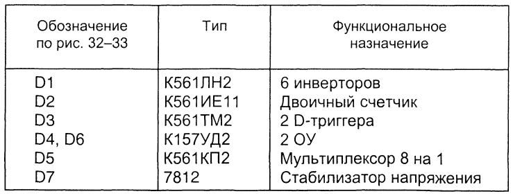
The types of chips used are listed in table. 6.
Table 6. The types of chips used
Instead of chips series C may use chipset series C. Can try to apply some chips series C or foreign counterparts series HH and HH.
Dual operational amplifiers (op amps) series C can be replaced by any similar the parameters of op-amp General purpose (with appropriate changes in the Pinout and the correction circuits).
To applied in the circuit of the differential magnetometer resistors are not required special requirements. They only need to have durable and miniature design and to be convenient for mounting. The nominal power dissipation of 0.125…0.25 W.
Potentiometers R5, R16 desirable multi-turn for ease of fine tuning device. The arm of potentiometer R5 must be made of plastic and needs to have a sufficient length to touch the hand of the operator when setting up do not caused change of the indicator at the expense of noise.
Capacitor C16 electrolytic of any small type.
The oscillatory circuit capacitors C2* and NW* consist of several (5-10 PCs) capacitors connected in parallel. Configuring the circuit in resonance occurs by adjusting the number of capacitors and their value. Recommended the type of capacitors K10-43, K71-7 or foreign thermostable counterparts. Can try to use a normal ceramic or metal film capacitors, however, the temperature fluctuations have usually adjust device.
Microammeter may be of any type for a current of 100 μa with a zero in the middle of the scale. Convenient small microammeter, for example, type M. You can use almost any microammeter, and even milliammeter - with any limit scale. For this we need to adjust the values resistors R15-R17.
Quartz resonator Q is any compact quartz clock (similar are also used in portable electronic games).
The switch S1 may be of any type, compact.
The sensor coil is made on a round ferrite cores with a diameter of 8 mm (used in magnetic antennas radios CB and LW bands) and a length of about 10 cm Each winding consists of exactly and tightly wound in two layers 200 turns of copper magnet wire with a diameter of 0,31 mm double lacquer-silk isolation. On top of all the windings is attached to the foil layer of the screen. The edge of the screen are isolated from each other to prevent a short-circuited revolution. The output of the screen is solid tinned copper wire. In case screen of aluminum foil this conclusion is superimposed on the screen at full length and tightly wound electrical tape. In the case of the screen of copper or brass foil conclusion soldered.
The ends of the ferrite cores fixed in Teflon centering disks through which each of the two halves of the sensor is fixed to the inside a plastic pipe of the PCB, which serves as a housing, as is schematically depicted in Fig. 34.
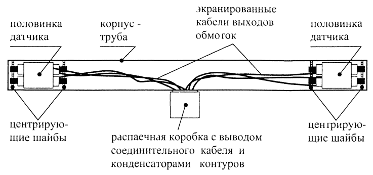
Fig. 34. Sensor design-antenna
The pipe length is about 60 cm, Each of the halves of the sensor located at the end of the pipe and further fixed with silicone sealant, which is filled in the space around the windings and their cores. Filling through special openings in the casing-pipe. Together with PTFE washers such sealant attaches to the mounting fragile ferrite cores the necessary elasticity, prevent them from cracking from accidental bumps.
The establishment of the device
1. Verify correct installation.
2. Monitor current consumption, which should not exceed 100 mA.
3. To check the correct operation of the master oscillator and the other elements the formation of the pulse signals.
4. To configure a resonant circuit of the sensor. Radiating at the frequency of 4 kHz, receiving and 8 kHz.
5. Verify correct operation of the amplification path and a synchronous detector.
Operation
How to configure and work with this device. We leave the place of the search, turn the device on and begin to rotate the antenna sensor. Best vertical plane passing through the direction North-South. If the sensor unit on the rod, you can not be rotated, and how to swing allows you to do post. The meter needle will deflect (compass effect). Using AC resistor R5 are trying to minimize the amplitude of these deviations. This will "move out of the" mid-point of the reading of the microammeter and it will also to adjust another variable resistor R16, which is designed to zero. When the "compass" effect will be minimal, the device is considered ambulanceman.
For small objects prospecting methods using differential magnetometer is not different from the methods of working with conventional metal detector. Near the object arrow may deviate in any direction. For large objects, the arrow indicator will be to deviate in different directions over a large area.
Author: A. I. Shchedrin