Functions and capabilities
A universal detector capable of detecting both small and large metallic objects. It has a number of replaceable coils with diameter from 25 to 250 mm. It can detect the location of small items with an accuracy of millimeters to several centimeters, and a large objects at a distance of several tens of centimeters.
Schematic diagram
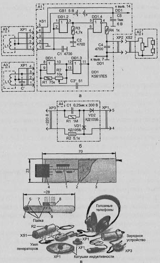
A schematic diagram is shown in Fig. 2.23, and. Its principle of operation traditional. The detector comprises a reference oscillator assembled from logic elements DD1.1 and DD1.3 with the generation frequency of about 100 kHz and metallokonstruktsy" the generator on the element DD1.2 and one of the external inductors, connected to the generator via connector XS1.
The signals from both generators are fed to the mixer, assembled on the element DD1.4. To the mixer output through a filter R4C4, "shear" the higher frequencies of the connected head phones. For more volume blasting phones are connected in series.
The metal detector is powered by battery GB1, but the power switch in its circuit no. - the supply voltage to the chip via pins 2, 4 when connecting replaceable coil.

Fig. 2.23. Universal detector: (a) schematic diagram; b - simple charger; in - circuit Board
The principle of operation
While near remote (replacement or retrieval) of the coil there is no metal in phones the sound will be quite certain tone set by the variable resistor R2. When approaching the same coil metal object to the tone of the sound will be to change.
Components and recommended replacement
Except as indicated on the diagram, you can use chips CLA, CLA, CLA. Fixed resistors - MLT-0,125, variable R2 SP5-2 or other small-sized. Oxide capacitor C5 can be K50-6, K53-1, other capacitors - KLS, km. Headphones - TONE-2A with volume control.
Head phones it is desirable to modify a little - set on the case volume control socket XS2 from small phones (in this nest insert the plug XP2 from the same phone), deleting the wire with fork. Then connect the caps in series. Power source - battery GB1 it is recommended to compile from four series-connected batteries D-0.1 or D-0,06. Since the batteries eventually depleted, for recharging the use a simple battery charger (Fig. 2.23, b) included in connector XS1 with five-pole plug.
The design of the metal detector
Details of the detector, in addition to connectors, battery and variable resistor, it is better just be mounted on a small printed circuit Board (Fig. 2.23 in). This fee along with the battery pack 2 should be placed in a small casing 3, for example, in box of medicines.
On the lid of the box must be secured connector 4, and through the hole in the bottom of the skip two-wire cord, the ends of the wires which are soldered to the connector XP2. AC resistor R2 needs to be fixed on the side wall of the box.
Winding the replaceable coils
For each of the replaceable coils need to be wound, the winding 5, which is winding layer varnished fabrics, and over - tinned copper foil 6. The beginning and the end winding of foil should not touch each other, so leave between them a gap of a few millimeters.
Then out of the foil material should make a base 7 in the form of a disk, on which the solder pin connector 8. The inner side of the base to leave on the edge of the ring, foil strip, not closed at the ends, and strip the conductor to the connector (with the stripe connect pins 2 and 4 of the connector).
To the base of the solder foil winding coils of the SJC that the gaps of the winding and annular strips of Foundation matched. If necessary on the basis to place the capacitor C', the conclusions of which need to solder to the terminals 3 and 1 connector, i.e. be connected parallel to the inductor.
After checking the coils (with an ohmmeter) and selection of the capacitor' (when establishing the metal detector) to solder the lid 9 of the foil material, made like the base with non-closed annular strip.
The coil shall contain such number of coils:
- for the coil diameter 25 mm - 150 turns of PEV-1 to 0.1;
- for the coil diameter 75 mm - 80 turns of PEV-1 0,18;
- for the coil diameter 200 mm - 50 turns of PEV-1 to 0.3.
Details of the charger can be placed in the same building that used for generators. The appearance of the nodes of the detector is shown in Fig. 2.23 V.
Setting of the metal detector
After producing one of the replacement coils, for example, the most compact, connect it to the connector XS1. The engine of the resistor R2 is set to the middle position and by connecting the headphones, the selection of capacitor NW to achieve low sound tones in them. When approaching the coil of a metal object the tone of the sound must change. Then make another coil diameter and not pripaivaya the cover, connect the coil to the connector XS1. It is desirable that the inductance the coil turned out to be 5-10% less than previously manufactured.
The selection of capacitor (if required) to achieve sound about the same tonality, as in the first case. Similarly, make and customize coils of other sizes.
Author: Nechaev I.


